58
SERVICING
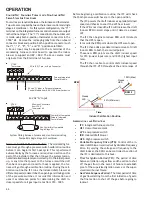
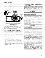
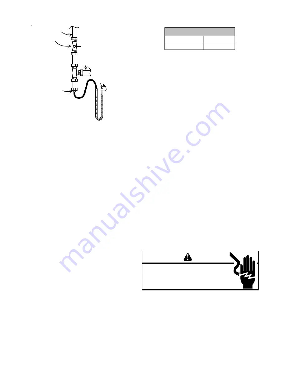
GAS LINE
GAS SHUTOFF VALVE
GAS LINE
TO FURNACE
DRIP LEG CAP
WITH FITTING
MANOMETER HOSE
MANOMETER
OPEN TO
ATMOSPHERE
Measuring Inlet Gas Pressure
(Alternate Method)
3. Turn ON the gas and electrical power supply and oper-
ate the furnace and all other gas consuming appliances
on the same gas supply line.
4. Measure furnace gas supply pressure with burners fir-
ing. Supply pressure must be within the range speci-
fied in the following table.
To test manifold pressure the furnace must be put into
“field test mode” to bring the furnace up to 100% input
.
5. Disconnect manometer after turning off gas at manual
shutoff valve. Reinstall plug before turning on gas to
furnace.
6. Turn OFF any unnecessary gas appliances started in
step 3.
7. Turn on gas to furnace and check for leaks. If leaks
are found, repair and then reinstall burner compart-
ment door.
8. Turn on electrical power and verify proper unit opera-
tion.
The gas valve is equipped with 1/8 NPT fittings to access
both the inlet and manifold gas pressures. To do a mani-
fold gas pressure check the furnace can be operated in
field test mode.
This mode will quickly bring the furnace
up to high fire. To enter field test mode; during a call for
heat, press the fault recall button twice within a five sec-
ond period; when the dual seven segment displays show
Ft, press the fault recall button again to enter field test
mode. The furnace will stay in field test for five minutes
or until the call for heat is satisfied. Gas valve orientation
must be such that the switch is facing out towards the
front of the furnace. Manifold pressure for natural gas is
pre-set to be between 3.2” WC to 3.8”WC. If the furnace
has been converted to LP gas, the manifold pressure will
be 9.7”WC to 10.3”W.
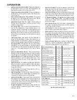
Natural Gas
3.5" w.c.
Propane Gas
10.0" w.c.
Manifold Gas Pressure
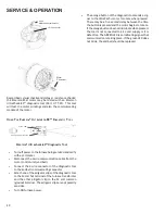
S-308 CHECKING HOT SURFACE IGNITOR
Modulating furnaces use a 115 volt silicon nitride hot sur-
face igniter. This is the familiar and reliable 0131F00008S
igniter with 17 second warm up time. At room tempera-
ture the igniter has a resistance range of 37 - 68 ohms.
The H.S.I. isconnected electrically to the IFC by a 3/16"
push-on connection.
S-309 CHECKING FOR FLASHBACK
Flashback will also cause burning in the burner venturi, but
is caused by the burning speed being greater than the gas-
air flow velocity coming from a burner port.
Flashback may occur at the moment of ignition, after a
burner heats up or when the burner turns off. The latter is
known as extinction pop.
Since the end results of flashback and delayed ignition can
be the same (burning in the burner venturi) a definite at-
tempt should be made to determine which has occurred. If
flashback should occur, check for the following:
1. Improper gas pressure - adjust to proper pressure (See
S-307 CHECKING GAS PRESSURE
)..
2. Check burner for proper alignment and/or replace
burner.
3. Improper orifice size - check orifice for obstruction.
S-310 CHECKING PRESSURE CONTROL
The pressure control is a safety device to prevent the com-
bustion cycle from occurring with inadequate venting caused
by a restricted or blocked vent pipe on the modulating fur-
nace. Also on the modulating furnaces there is a pressure
control that will prevent the combustion cycle from occur-
ring with inadequate condensate drainage due to a partial
or blocked recuperator coil or drain.
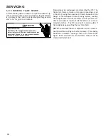
WARNING
HIGH
VOLTAGE
D
ISCONNECT
ALL
POWER BEFORE SERVICING OR
INSTALLING THIS UNIT.
M
ULTIPLE POWER SOURCES MAY
BE PRESENT.
F
AILURE TO DO SO MAY CAUSE PROPERTY
DAMAGE, PERSONAL INJURY OR DEATH.
1. Remove burner compartment door to gain access to
pressure switch(es).
2. Remove wires from the pressure switch(es) electrical
terminals.
3. Using a VOM check from common terminal to NO (Nor-
mally Open) - should read open.

