20
Improved construction and additional insulation in buildings
have reduced heat loss by reducing air infiltration and escape
around doors and windows. These changes have helped in
reducing heating/cooling costs but have created a problem
supplying combustion and ventilation air for gas fired and other
fuel burning appliances. Appliances that pull air out of the
house (clothes dryers, exhaust fans, fireplaces, etc.) increase
the problem by starving appliances for air.
House depressurization can cause back drafting or improper
combustion of gas-fired appliances, thereby exposing building
occupants to gas combustion products that could include car-
bon monoxide.
If this furnace is to be installed in the same space with other
gas appliances, such as a water heater, ensure there is an
adequate supply of combustion and ventilation air for the other
appliances. Refer to the latest edition of the National Fuel
Gas Code NFPA 54/ANSI Z223.1 or CAN/CSA B149 Installation
Codes or applicable provisions of the local building codes for
determining the combustion air requirements for the appli-
ances.
Most homes will require outside air be supplied to the furnace
area by means of ventilation grilles or ducts connecting di-
rectly to the outdoors or spaces open to the outdoors such as
attics or crawl spaces.
Installation Positions
DM97MC models may be installed up flow or horizontally
with left or right side down. DC97MC models may be in-
stalled down flow or horizontally with left or right side down.
Do not install any furnace on its back.
Horizontal Installations
1. Horizontal installations require 5.5" under the furnace
to accommodate the drain trap.
2. Horizontal furnaces must be installed with ¾” slope
from back to front to permit condensate flow towards
the front of the furnace.
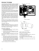
When installing a DM97MC horizontally with the left side
down, there are two options for connecting the vent pipe to
the furnace.
1. Venting may be connected to the furnace vent pipe fit-
ting on the original top (now the end) of the furnace
2. The internal vent pipe and elbow may be removed from
the furnace to permit the vent to exit the top (original
side) of the furnace. If this option is used, an RF000142
Vent-Drain coupling must be used to keep condensate
from collecting in the inducer assembly.
Refer to the following instructions and illustration.
Insert flange. Cut 2 ½” long.
R 000142
F
Horizontal Installation
C
U
T
H
E
R
E
Vent/Flue Pipe Cuts
1. Remove screws from vent flange.
2. Remove internal elbow and vent pipe.
3. Cut pipe 2 1/2” from flange.
4. Remove cabinet plug adjacent to inducer outlet and in-
stall an original cabinet vent hole.
5. Install RF000142 coupling on inducer outlet.
6. Install flanged vent section removed in step 2 & secure
with clamps.
7. Secure flange to cabinet using screws removed in step
1.
PRODUCT DESIGN

