DCC601A51
intelligent Tab Controller
4P420109-1 – 2015.10
Installer reference guide
8
7.
Electric wiring
This chapter will describe the procedure to connect the intelligent Tab
Controller kit components with Daikin devices and other equipment.
7.1.
Connecting to other equipment
For all wiring requirements, refer to
"15.8. Wiring requirements" on
7.1.1.
Connecting DIII-NET compatible equipment
DIII-NET is a unique air conditioning equipment communication
capability developed by Daikin. Using DIII-NET, you can centrally
control multiple DIII-NET-compatible air conditioning devices by
connecting them to your intelligent Tab Controller.
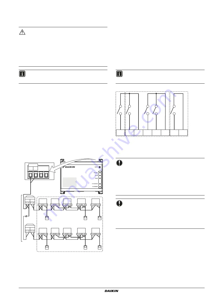
To connect the DIII-NET communication line, use the F1 and F2
terminals on the upper part of the I/O module, as shown on the
following diagram.
These two terminals have no polarity. An example of connecting
more than two air conditioning devices is shown in the following
wiring diagram.
Schematic wiring diagram with DIII terminals
a
Outdoor unit
b
OUT - OUT
c
IN - OUT
d
Indoor unit
e
A maximum of 7 outdoor units can be connected.
f
A maximum of 32 indoor units can be connected
(a unique DIII address is required for each unit).
7.1.2.
Connecting digital input and output devices
The intelligent Tab Controller can be connected with an external
signal input device for stopping air conditioners, with electric energy
meters for calculating the electricity usage of individual air
conditioners or other devices.
Connect the contact input lines or pulse input lines to the Di1, Di2,
Di3, Di4 and COM terminals of the connector on the bottom of the I/O
module. The function of each terminal is as shown in the following
wiring diagram.
The function assignment, however, may be changed at a later time.
For more details on the required pulse width and interval, refer to
"15.8. Wiring requirements" on page 26
. For how to change the
function assignment, refer to
"10.2.6. Management points attribute
Schematic wiring diagram with Di and Do terminals
a [Di1]
Forced stop contact input (normally open).
b [Di2] [Di3] [Di4]
Digital inputs. Can be configured as
normally open (A-type) or normally closed (B-type) contact
inputs, or as pulse inputs.
c [Do]
Provided for future use.
WARNING
Do not turn on the power supply before all wire
connections are completed. Not doing so may cause an
electric shock.
After the wiring is completed, double-check that all wires
are connected correctly before turning on the power
supply.
All field supplied parts, materials and electric works must
comply with the applicable legislation.
INFORMATION
At the time of writing, some connectors are not active, but
provided for future use.
a
b
c
d
e
f
d
d
d
d
d
d
d
d
d
a
b
c
DIII
F2 F1
INFORMATION
At the time of writing, the digital output connection Do is
not active, but provided for future use.
NOTICE
When the forced stop contact input is closed, a stop
signal is sent to all connected devices. There is no
hard guarantee that all devices are actually stopped
and remain stopped during the time the forced stop
contact input is active.
When the forced stop contact input is closed, the
connected devices cannot be restarted unless the
contact input is reopened.
NOTICE
The COM terminals are all connected internally. So,
you can use any one of them. However, you can only
connect up to two wires simultaneously to each COM
terminal.
If applicable, connect the I/O module’s COM terminal
to the negative side of the device terminals.
Di1
Di2
COM
Di3
Di4
COM
COM
Do
a
b
c


