4
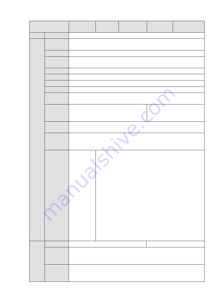
Model
NVR608-32-
4KS2
NVR608-6
4-4KS2
NVR608-128-
4KS2
NVR608R-6
4-4KS2
NVR608R-128-
4KS2
Mode
Network
Protocol
SNMP/FTP/ISCSI/UPNP
SATA Port
8
eSATA
Port
1
RS232 Port
1 RS232 port. To debug and transmit COM data.
RS485 Port
1 RS485 port. To control peripheral PTZ and etc. Support various protocols.
USB Port
2 USB 2.0 ports and 2 USB3.0 ports.
HDMI Port
2 HDMI ports
Network
Port
2 RJ45 10/100/1000Mbps self-adaptive Ethernet ports
Power
On-off
Button
One at the front panel.
N/A
Power
Button
One at the front panel.
IR Remote
Control
Receiver
N/A
Indicator
Light
1 HDD
alarm
indicator
light
1 system
running
status
indicator
light
1
network
alarm
indicator
light
1 power
light
1 HDD alarm indicator light
1 alarm indicator light
1 network alarm indicator light
1 power light
Gener
al
Para
meter
s
Power
AC110~240V
,
50~60Hz
AC100~240V
,
50~60Hz
Power
Consumpti
on
<
20W
(
No HDD
)
, <90w
(
4T*8
)
Working
Temperatu
re
-10
℃
~
+55
℃
Содержание NVR608-32-4KS2
Страница 1: ...I Network Video Recorder User s Manual V6 0 0 ZHEJIANG DAHUA VISION TECHNOLOGY CO LTD...
Страница 56: ...40 Figure 3 14 Step 2 Click Add new holiday button and device displays the following interface See Figure 3 15...
Страница 121: ...105 Figure 3 92 Figure 3 93...
Страница 144: ...128 Figure 3 111 Figure 3 112 Figure 3 113...
Страница 157: ...141 Figure 3 126 Figure 3 127...
Страница 159: ...143 Figure 3 129 Click draw button to draw the zone See Figure 3 130 Figure 3 130...
Страница 162: ...146 Figure 3 133 Click Draw button to draw a zone See Figure 3 134 Figure 3 134...
Страница 167: ...151 Figure 3 139 Click draw button to draw the zone See Figure 3 140...
Страница 178: ...162 Figure 3 151 Step 2 Add surveillance scene 1 Click Add The Add interface is displayed See Figure 3 152...
Страница 185: ...169 Figure 3 157 Figure 3 158...
Страница 186: ...170 Figure 3 159 Figure 3 160...
Страница 189: ...173 Figure 3 164 Figure 3 165...
Страница 224: ...208 Figure 3 199...
Страница 231: ...215 Figure 3 206 Step 2 Click Add user button in Figure 3 206 The interface is shown as in Figure 3 207 Figure 3 207...
Страница 247: ...231 Figure 3 227 Step 2 Click Add group Enter add group interface See Figure 3 228 Figure 3 228...
Страница 311: ...295 Figure 4 56 Figure 4 57...
Страница 317: ...301 Figure 4 62 Figure 4 63...
Страница 318: ...302 Figure 4 64 Figure 4 65...
Страница 343: ...327 Figure 4 101 Figure 4 102...
Страница 352: ...336 Figure 4 115 Figure 4 116...
Страница 372: ...356 Figure 4 144 Note For admin you can change the email information See Figure 4 145...


