140
Now the icon is shown as
. Click
to delete a record type from one period.
In Figure 3-113. Click button
after one date or a holiday, you can see an interface shown
as in Figure 3-114.
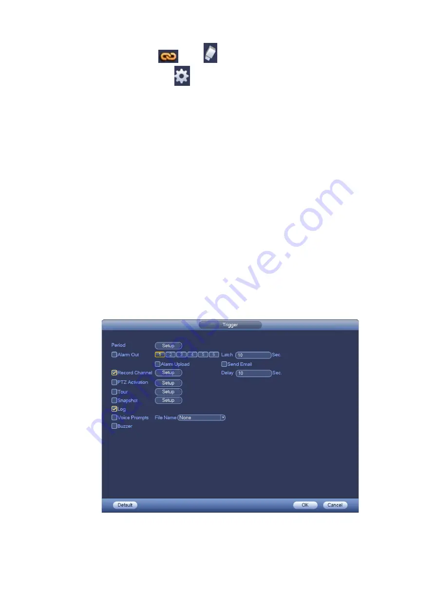
Alarm output: when an alarm occurs, system enables peripheral alarm devices.
Latch: when tripwire complete, system auto delays detecting for a specified time. The value ranges
from 1-300(Unit: second)
Show message: System can pop up a message to alarm you in the local host screen if you enabled
this function.
Alarm upload: System can upload the alarm signal to the network (including alarm center) if you
enabled current function.
Send email: System can send out email to alert you when an alarm occurs.
Record channel: System auto activates tripwire channel(s) to record once an alarm occurs. Please
make sure you have set intelligent record in Schedule interface(Main Menu->Setting->Schedule)
and schedule record in manual record interface(Main Menu->Advanced->Manual Record)
PTZ activation: Here you can set PTZ movement when an alarm occurs. Such as go to preset, tour
&pattern when there is an alarm. Click “select” button, you can see an interface is shown as in
Record Delay: System can delay the record for specified time after alarm ended. The value ranges
from 10s to 300s.
Tour: Here you can enable tour function when an alarm occurs. System one-window tour.
Snapshot: You can enable this function to snapshot image when a motion detect alarm occurs.
Buzzer: Highlight the icon to enable this function. The buzzer beeps when an alarm occurs.
Figure 3-125
Содержание NVR608-32-4KS2
Страница 1: ...I Network Video Recorder User s Manual V6 0 0 ZHEJIANG DAHUA VISION TECHNOLOGY CO LTD...
Страница 56: ...40 Figure 3 14 Step 2 Click Add new holiday button and device displays the following interface See Figure 3 15...
Страница 121: ...105 Figure 3 92 Figure 3 93...
Страница 144: ...128 Figure 3 111 Figure 3 112 Figure 3 113...
Страница 157: ...141 Figure 3 126 Figure 3 127...
Страница 159: ...143 Figure 3 129 Click draw button to draw the zone See Figure 3 130 Figure 3 130...
Страница 162: ...146 Figure 3 133 Click Draw button to draw a zone See Figure 3 134 Figure 3 134...
Страница 167: ...151 Figure 3 139 Click draw button to draw the zone See Figure 3 140...
Страница 178: ...162 Figure 3 151 Step 2 Add surveillance scene 1 Click Add The Add interface is displayed See Figure 3 152...
Страница 185: ...169 Figure 3 157 Figure 3 158...
Страница 186: ...170 Figure 3 159 Figure 3 160...
Страница 189: ...173 Figure 3 164 Figure 3 165...
Страница 224: ...208 Figure 3 199...
Страница 231: ...215 Figure 3 206 Step 2 Click Add user button in Figure 3 206 The interface is shown as in Figure 3 207 Figure 3 207...
Страница 247: ...231 Figure 3 227 Step 2 Click Add group Enter add group interface See Figure 3 228 Figure 3 228...
Страница 311: ...295 Figure 4 56 Figure 4 57...
Страница 317: ...301 Figure 4 62 Figure 4 63...
Страница 318: ...302 Figure 4 64 Figure 4 65...
Страница 343: ...327 Figure 4 101 Figure 4 102...
Страница 352: ...336 Figure 4 115 Figure 4 116...
Страница 372: ...356 Figure 4 144 Note For admin you can change the email information See Figure 4 145...


