198
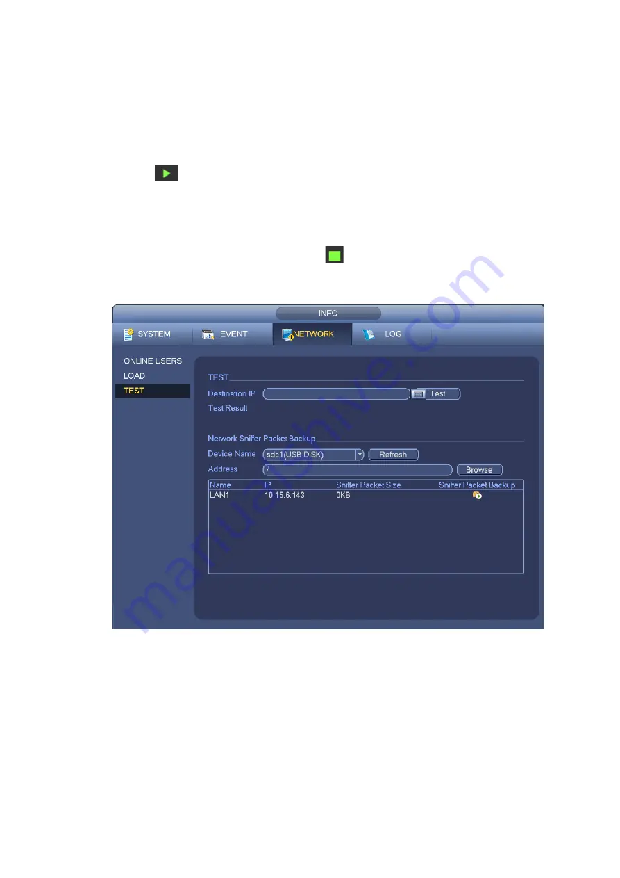
average delay and packet loss rate and you can also view the network status as OK, bad, no
connection and etc.
Network Sniffer backup: Please insert USB2.0 device and click the Refresh button, you can view the
device on the following column. You can use the dropdown list to select peripheral device. Click
Browse button to select the snap path. The steps here are same as preview backup operation.
You can view all connected network adapter names (including Ethernet, PPPoE, WIFI, and 3G), you can
click the button
on the right panel to begin Sniffer. Click the grey stop button to stop. Please note
system can not Sniffer several network adapters at the same time.
After Sniffer began, you can exit to implement corresponding network operation such as login WEB,
monitor. Please go back to Sniffer interface to click
stop Sniffer. System can save the packets to the
specified path. The file is named after “Network adapter name+time”. You can use software such as
Wireshark to open the packets on the PC for the professional engineer to solve complicated problems.
Figure 3-189
3.11.2.2 Network Load
From main menu>Info>Network>Load, network load is shown as in Figure 3-190. Here you can view the
follow statistics of the device network adapter.
Here you can view information of all connected network adapters. The connection status is shown as
offline if connection is disconnected. Click one network adapter, you can view the flow statistics such as
send rate and receive rate at the top panel
Содержание NVR608-32-4KS2
Страница 1: ...I Network Video Recorder User s Manual V6 0 0 ZHEJIANG DAHUA VISION TECHNOLOGY CO LTD...
Страница 56: ...40 Figure 3 14 Step 2 Click Add new holiday button and device displays the following interface See Figure 3 15...
Страница 121: ...105 Figure 3 92 Figure 3 93...
Страница 144: ...128 Figure 3 111 Figure 3 112 Figure 3 113...
Страница 157: ...141 Figure 3 126 Figure 3 127...
Страница 159: ...143 Figure 3 129 Click draw button to draw the zone See Figure 3 130 Figure 3 130...
Страница 162: ...146 Figure 3 133 Click Draw button to draw a zone See Figure 3 134 Figure 3 134...
Страница 167: ...151 Figure 3 139 Click draw button to draw the zone See Figure 3 140...
Страница 178: ...162 Figure 3 151 Step 2 Add surveillance scene 1 Click Add The Add interface is displayed See Figure 3 152...
Страница 185: ...169 Figure 3 157 Figure 3 158...
Страница 186: ...170 Figure 3 159 Figure 3 160...
Страница 189: ...173 Figure 3 164 Figure 3 165...
Страница 224: ...208 Figure 3 199...
Страница 231: ...215 Figure 3 206 Step 2 Click Add user button in Figure 3 206 The interface is shown as in Figure 3 207 Figure 3 207...
Страница 247: ...231 Figure 3 227 Step 2 Click Add group Enter add group interface See Figure 3 228 Figure 3 228...
Страница 311: ...295 Figure 4 56 Figure 4 57...
Страница 317: ...301 Figure 4 62 Figure 4 63...
Страница 318: ...302 Figure 4 64 Figure 4 65...
Страница 343: ...327 Figure 4 101 Figure 4 102...
Страница 352: ...336 Figure 4 115 Figure 4 116...
Страница 372: ...356 Figure 4 144 Note For admin you can change the email information See Figure 4 145...


