


293
Parameter
Description
When one of the comparison objects is a spot, both the highest
temp and lowest temp is the average temp.
Alarm Condition
The condition to trigger the alarm, including higher, lower and
match.
Alarm temp
threshold
The temp to trigger the alarm. The range is 0
℃
-550
℃
.
Step 3 Click OK to complete the setting.
Step 4 After the settin, you can view the temp comparison results on the preview interface on the left of
the window.
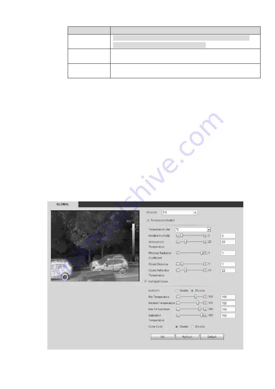
4.6.3.3 Global
You can enable temperature switch, isotherm and color code.
After enabling the temperature switch, temp rule comes into effect and the preset temp rule is
displayed on the window.
The isotherm function is mainly used for the objects that need to be highlighted in the highlight
screen. The median temperature is taken as the reference, the upper limit temperature and lower
limit temperature as the floating range, and those above the lower limit temperature are represented
by bright colors, while those below the lower limit are shown as black and white.
When
the color code is enabled, the corresponding color bar is displayed on the right side of the
monitoring interface to indicate the color change between the lowest temperature and the highest
temperature.
Step 1 Select Setup > Temperature Measurement > Global.
The Global interface is displayed. See Figure 4-55
Figure 4-55
Содержание NVR608-32-4KS2
Страница 1: ...I Network Video Recorder User s Manual V6 0 0 ZHEJIANG DAHUA VISION TECHNOLOGY CO LTD...
Страница 56: ...40 Figure 3 14 Step 2 Click Add new holiday button and device displays the following interface See Figure 3 15...
Страница 121: ...105 Figure 3 92 Figure 3 93...
Страница 144: ...128 Figure 3 111 Figure 3 112 Figure 3 113...
Страница 157: ...141 Figure 3 126 Figure 3 127...
Страница 159: ...143 Figure 3 129 Click draw button to draw the zone See Figure 3 130 Figure 3 130...
Страница 162: ...146 Figure 3 133 Click Draw button to draw a zone See Figure 3 134 Figure 3 134...
Страница 167: ...151 Figure 3 139 Click draw button to draw the zone See Figure 3 140...
Страница 178: ...162 Figure 3 151 Step 2 Add surveillance scene 1 Click Add The Add interface is displayed See Figure 3 152...
Страница 185: ...169 Figure 3 157 Figure 3 158...
Страница 186: ...170 Figure 3 159 Figure 3 160...
Страница 189: ...173 Figure 3 164 Figure 3 165...
Страница 224: ...208 Figure 3 199...
Страница 231: ...215 Figure 3 206 Step 2 Click Add user button in Figure 3 206 The interface is shown as in Figure 3 207 Figure 3 207...
Страница 247: ...231 Figure 3 227 Step 2 Click Add group Enter add group interface See Figure 3 228 Figure 3 228...
Страница 311: ...295 Figure 4 56 Figure 4 57...
Страница 317: ...301 Figure 4 62 Figure 4 63...
Страница 318: ...302 Figure 4 64 Figure 4 65...
Страница 343: ...327 Figure 4 101 Figure 4 102...
Страница 352: ...336 Figure 4 115 Figure 4 116...
Страница 372: ...356 Figure 4 144 Note For admin you can change the email information See Figure 4 145...


