350
mode.
Customized: You can set the gain of the red/blue channel.
The value reneges from 0 to 100.
Day/Night
It is to set device color and the B/W mode switch. The default
setup is auto.
Color: Device outputs the color video.
Auto: Device auto select to output the color or the B/W
video according to the device feature (The general bright of
the video or there is IR light or not.)
B/W: The device outputs the black and white video.
Sensor: It is to set when there is peripheral connected IR
light.
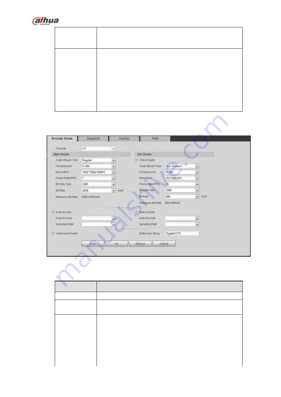
5.10.1.3 Encode
5.10.1.3.1 Encode
The encode interface is shown as below. See Figure 5-27.
Figure 5-27
Please refer to the following sheet for detailed information.
Parameter
Function
Channel
Please select a channel from the dropdown list.
Video enable
Check the box here to enable extra stream video. This item is
enabled by default.
Code
stream
type
It includes main stream, motion stream and alarm stream. You
can select different encode frame rates form different recorded
events.
System supports active control frame function (ACF). It allows
you to record in different frame rates.
For example, you can use high frame rate to record important
events, record scheduled event in lower frame rate and it allows
Содержание NVR1A-4P Series
Страница 1: ...Dahua Network Video Recorder User s Manual V 4 3 0 ...
Страница 138: ...124 Figure 3 5 3 6 6 NVR42N Series Please refer to Figure 3 6 for connection sample Figure 3 6 ...
Страница 142: ...128 Figure 3 11 3 6 12 NVR42V 8P Series Please refer to Figure 3 12 for connection sample ...
Страница 143: ...129 Figure 3 12 ...
Страница 157: ...143 Figure 4 15 Step 2 Click device display edit interface See Figure 4 16 ...
Страница 220: ...206 Figure 4 93 Figure 4 94 ...
Страница 240: ...226 Figure 4 110 Figure 4 111 Figure 4 112 ...
Страница 251: ...237 Figure 4 123 Figure 4 124 ...
Страница 253: ...239 Figure 4 126 Click draw button to draw the zone See Figure 4 127 ...
Страница 257: ...243 Figure 4 130 Click Draw button to draw a zone See Figure 4 131 Figure 4 131 ...
Страница 262: ...248 Figure 4 136 Click draw button to draw the zone See Figure 4 137 ...
Страница 275: ...261 Figure 4 148 Figure 4 149 ...
Страница 276: ...262 Figure 4 150 Figure 4 151 ...
Страница 387: ...373 Figure 5 60 Figure 5 61 ...
Страница 388: ...374 Figure 5 62 Figure 5 63 ...
Страница 412: ...398 Figure 5 96 Figure 5 97 ...
Страница 418: ...404 Figure 5 106 5 10 4 4 Record Control The interface is shown as in Figure 5 107 Figure 5 107 ...


