background image

xStack

® 

DGS-3620 Series Layer 3 Managed Stackable Gigabit Switch Web UI Reference Guide 

45 


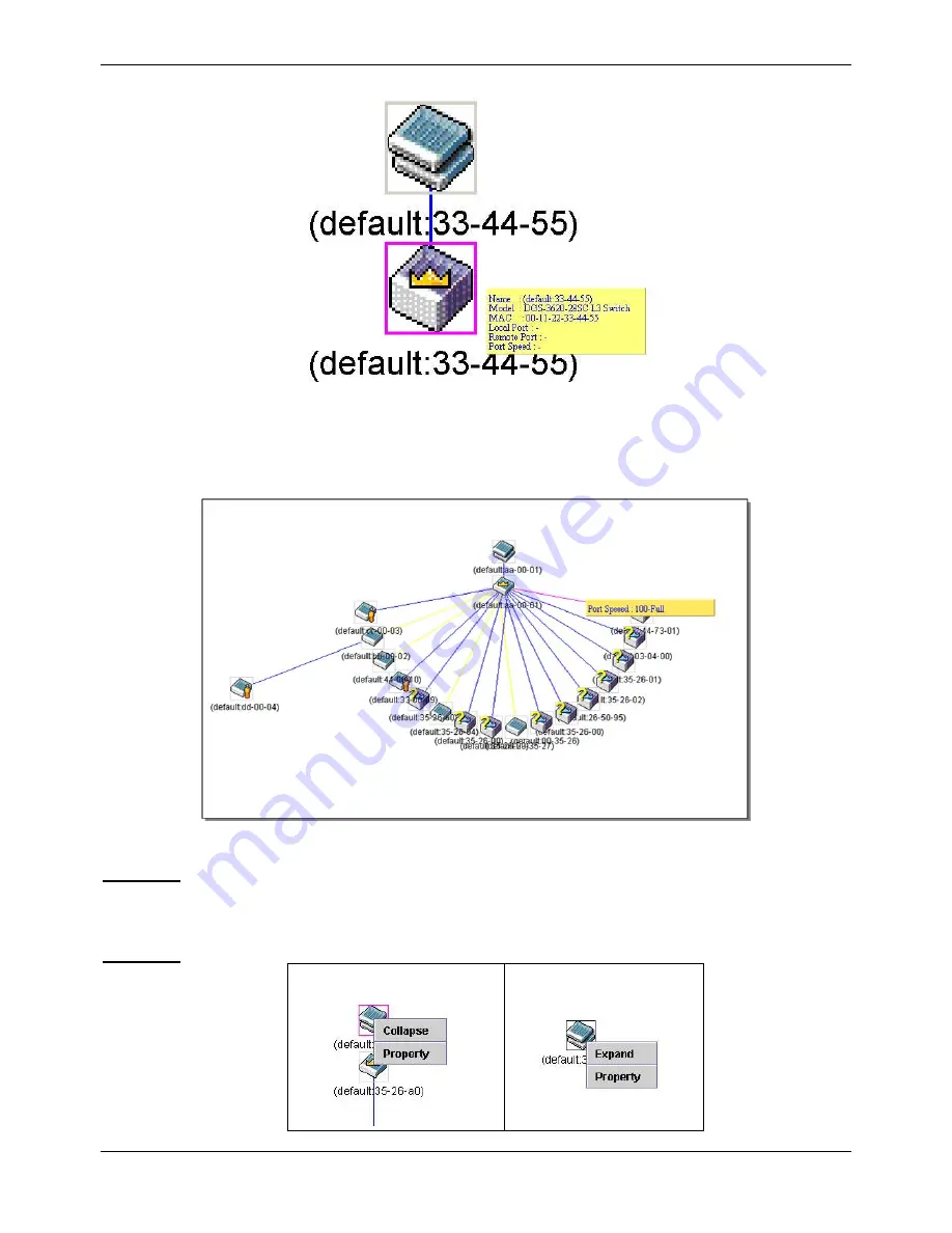
Figure 3-22 Device Information Utilizing the Tool Tip 


Setting the mouse cursor over a line between two devices will display the connection speed between the two 
devices, as shown below. 


Figure 3-23 Port Speed Utilizing the Tool Tip 


Right-clicking on a device will allow the user to perform various functions, depending on the role of the Switch in 
the SIM group and the icon associated with it. 

Right-Click 


Group Icon 


Содержание xStack DGS-3620-52P

Страница 1: ......

Страница 2: ...f D Link Corporation is strictly forbidden Trademarks used in this text D Link and the D LINK logo are trademarks of D Link Corporation Microsoft and Windows are registered trademarks of Microsoft Cor...

Страница 3: ...System Information Settings 9 Port Configuration 9 Port Settings 9 Port Description Settings 11 Port Error Disabled 12 Port Auto Negotiation Information 13 Jumbo Frame Settings 14 PoE 14 PoE System S...

Страница 4: ...Traps Settings 51 SNMP Linkchange Traps Settings 51 SNMP View Table Settings 52 SNMP Community Table Settings 53 SNMP Group Table Settings 54 SNMP Engine ID Settings 55 SNMP User Table Settings 55 SNM...

Страница 5: ...g 112 Multicast VLAN 119 Multicast Filtering 125 IPv4 Multicast Filtering 125 IPv6 Multicast Filtering 127 Multicast Filtering Mode 130 ERPS Settings 130 LLDP 134 LLDP 134 LLDP MED 142 NLB FDB Setting...

Страница 6: ...231 BGP Global Settings 232 BGP Aggregate Address Settings 233 BGP Network Settings 234 BGP Dampening Settings 235 BGP Peer Group Settings 236 BGP Neighbor 237 BGP Reflector Settings 245 BGP Confeder...

Страница 7: ...file 298 Adding a CPU Packet Content ACL Profile 301 ACL Finder 304 ACL Flow Meter 304 Egress Access Profile List 307 Adding an Ethernet ACL Profile 308 Adding an IPv4 Egress ACL Profile 311 Adding an...

Страница 8: ...ngs 360 Port Security Entries 361 ARP Spoofing Prevention Settings 361 BPDU Attack Protection 362 Loopback Detection Settings 364 Traffic Segmentation Settings 365 NetBIOS Filtering Settings 366 DHCP...

Страница 9: ...CFM Port Settings 415 CFM MIPCCM Table 416 CFM Loopback Settings 416 CFM Linktrace Settings 417 CFM Packet Counter 418 CFM Fault Table 418 CFM MP Table 419 Ethernet OAM 419 Ethernet OAM Settings 419...

Страница 10: ...irmware 449 Upload Firmware to TFTP 449 Upload Firmware to RCP 450 Upload Firmware to HTTP 451 Download Configuration 451 Download Configuration from TFTP 451 Download Configuration from RCP 452 Downl...

Страница 11: ...mail Bold font is also used to represent filenames program names and commands For example use the copy command Boldface Typewriter Font Indicates commands and responses to prompts that must be typed e...

Страница 12: ...tch the power available at the Switch s location o 115 volts V 60 hertz Hz in most of North and South America and some Far Eastern countries such as South Korea and Taiwan o 100 V 50 Hz in eastern Jap...

Страница 13: ...and that the full weight of the rack rests on the floor Install front and side stabilizers on a single rack or front stabilizers for joined multiple racks before working on the rack Always load the r...

Страница 14: ...assis The following steps can also be taken prevent damage from electrostatic discharge ESD 1 When unpacking a static sensitive component from its shipping carton do not remove the component from the...

Страница 15: ...to access the same internal switching software and configure it Thus all settings encountered in web based management are the same as those found in the console program Login to the Web Manager To beg...

Страница 16: ...he table Figure 1 2 Main Web Manager page Area Number Function Area 1 Select the menu or window to display Open folders and click the hyperlinked menu buttons and subfolders contained within them to d...

Страница 17: ...ing the Layer 2 functionality of the Switch L3 Features In this section the user will be able to configure features regarding the Layer 3 functionality of the Switch QoS In this section the user will...

Страница 18: ...witch To return to the Device Information window after viewing other windows click the DGS 3620 Series link The Device Information window shows the Switch s MAC Address assigned by the factory and unc...

Страница 19: ...ow Figure 2 2 System Information Settings window The fields that can be configured are described below Parameter Description System Name Enter a system name for the Switch if so desired This name will...

Страница 20: ...devices in full or half duplex except 1000 Mbps which is always full duplex The Auto setting allows the port to automatically determine the fastest settings the device the port is connected to can ha...

Страница 21: ...MDI mode on another switch through a cross over cable Cross Select cross for cross cabling If set to cross state the port is in MDIX mode and can be connected to a port in MDI mode on another switch t...

Страница 22: ...configuring the Combo ports the Medium Type defines the type of transport medium to be used whether Copper or Fiber Description Users may then enter a description for the chosen port s Click the Appl...

Страница 23: ...d or disabled Reason Describe the reason why the port has been error disabled such as it has become a shutdown port for storm control Port Auto Negotiation Information The following window displays th...

Страница 24: ...ult is Disabled When disabled the maximum frame size is 1536 bytes When enabled the maximum frame size is 13312 bytes Unit Select the unit you wish to configure From Port To Port Select the appropriat...

Страница 25: ...below Figure 2 8 PoE System Settings window The following parameters can be configured Parameter Description Unit Select the unit you wish to configure Tick the All check box to select all units Power...

Страница 26: ...le ports happen to have the same level of priority the port ID will be used to determine the priority The lower port ID has higher priority The setting of priority will affect the order of supplying p...

Страница 27: ...fined Choose from the following options 2 5 10 15 minutes or Never The default setting is 10 minutes Data Bits Display the data bits used for the serial port connection Parity Bits Display the parity...

Страница 28: ...anges made Save Mode Use the drop down menu to choose the method for saving the switch log to the flash memory The user has three options On Demand Users who choose this method will only save log file...

Страница 29: ...slog server Facility Use the drop down menu to select Local 0 Local 1 Local 2 Local 3 Local 4 Local 5 Local 6 or Local 7 UDP Port 514 or 6000 65535 Type the UDP port number used for sending Syslog mes...

Страница 30: ...time in days hours minutes and seconds since the Switch was last restarted Level Display the level of the log entry Log Text Display text describing the event that triggered the history log entry Cli...

Страница 31: ...to an SNMP agent and the Switch s log for analysis Severity Level This drop down menu allows you to select the level of messages that will be sent The options are Emergency 0 Alert 1 Critical 2 Error...

Страница 32: ...ayed in the Time Range Information table in the bottom half of the window shown above Port Group Settings This window is used to create port groups and add or delete ports from the port groups To view...

Страница 33: ...Admin Operator Power User User Configuration Read Write Read Write partly Read Write partly No Network Monitoring Read Write Read Write Read only Read only Community Strings and Trap Stations Read Wr...

Страница 34: ...ill not be logged When the user uses AAA authentication to logged in the user name should not be changed if the user has used the Enable Admin function to replace its privilege Stacking From firmware...

Страница 35: ...through an election process which determines the second lowest MAC address and then will assign that switch as the Backup Master if all priorities are the same The Backup master are physically display...

Страница 36: ...cleared as well If the Backup Master has been hot removed a new Backup Master will be chosen through the election process previously described Switches in the stack will clear the configurations of t...

Страница 37: ...ill become zero after the stacking has stabilized Current Box ID The Box ID of the switch in the stack to be configured New Box ID The new box ID of the selected switch in the stack that was selected...

Страница 38: ...is entered and is used to translate IP addresses to MAC addresses To view the following window click Management ARP Static ARP Settings as show below Figure 3 1 Static ARP Settings window The fields...

Страница 39: ...the source IP and destination IP are in the same interface To view the following window click Management ARP Proxy ARP Settings as show below Figure 3 2 Proxy ARP Settings window Click the Edit butto...

Страница 40: ...ived an ARP request packet that is sent by an IP address that match the system s own IP address In this case the system knows that somebody out there uses an IP address that is conflict with the syste...

Страница 41: ...equest will not be sent periodically By default the interval time is 0 Click the Apply button located in the Gratuitous ARP Trap Log section to accept the changes made in this section Click the Apply...

Страница 42: ...eb manager will display the Switch s current IP settings NOTE The Switch s factory default IP address is 10 90 90 90 with a subnet mask of 255 0 0 0 and a default gateway of 0 0 0 0 To view the follow...

Страница 43: ...etwork 255 255 0 0 for a Class B network and 255 255 255 0 for a Class C network but custom subnet masks are allowed Gateway IP address that determines where packets with a destination address outside...

Страница 44: ...n menu to enable or disable the Interface Admin State Secondary Interface Tick the check box to use this Interface as a Secondary Interface Click the Apply button to accept the changes made Click the...

Страница 45: ...IPv6 interface name IPv6 State Use the drop down menu to enable or disable IPv6 State Interface Admin State Use the drop down menu to enable or disable the Interface Admin State IPv6 Network Address...

Страница 46: ...ending unsolicited multicast Router Advertisements from the interface in seconds It must be no less than 3 seconds and no greater than 75 MaxRtrAdvInterval The default is 0 33 MaxRtrAdvInterval Max Ro...

Страница 47: ...its name can t be a duplicate with the regular ipif IPv4 Address Enter a 32 bit IPv4 address for the loopback interface Subnet Mask Enter a subnet mask to be applied to the loopback interface Interfa...

Страница 48: ...he console CLI Paging is Enabled by default To disable it click the Disabled radio button DHCP Auto Configuration State Enable or disable the Switch s DHCP auto configuration feature When enabled the...

Страница 49: ...n to accept the changes made Session Table Users can display the management sessions since the Switch was last rebooted To view the following window click Management Session Table as show below Figure...

Страница 50: ...through its management VLAN 2 Member Switch MS This is a switch that has joined a single IP group and is accessible from the CS and it takes on the following characteristics a It is not a CS or MS of...

Страница 51: ...tomatically No configuration will be necessary to rediscover these switches There are some instances where pre saved MS switches cannot be rediscovered For example if the Switch is still powered down...

Страница 52: ...val 30 90 The user may set the discovery protocol interval in seconds that the Switch will send out discovery packets Returning information to a Commander Switch will include information about other s...

Страница 53: ...l Port Displays the number of the physical port on the CS that the MS or CaS is connected to The CS will have no entry in this field Speed Displays the connection speed between the CS and the MS or Ca...

Страница 54: ...ch Layer 2 commander switch Member switch of other group Layer 3 commander switch Layer 2 candidate switch Commander switch of other group Layer 3 candidate switch Layer 2 member switch Unknown device...

Страница 55: ...the mouse cursor over a line between two devices will display the connection speed between the two devices as shown below Figure 3 23 Port Speed Utilizing the Tool Tip Right clicking on a device will...

Страница 56: ...d with the last six digits of the MAC Address to identify it Module Name Displays the full module name of the switch that was right clicked MAC Address Displays the MAC Address of the corresponding Sw...

Страница 57: ...e 3 28 Right clicking a Candidate icon The following options may appear for the user to configure Collapse To collapse the group that will be represented by a single icon Expand To expand the SIM grou...

Страница 58: ...the views with the latest status View Topology Display the Topology view About Will display the SIM information including the current SIM version Help Figure 3 32 About window Firmware Upgrade This s...

Страница 59: ...Management Protocol SNMP is an OSI Layer 7 Application Layer designed specifically for managing and monitoring network devices SNMP enables network management stations to read and modify the settings...

Страница 60: ...rap recipient or network manager Typical traps include trap messages for Authentication Failure Topology Change and Broadcast Multicast Storm Traps The Switch in the Management Information Base MIB st...

Страница 61: ...ields that can be configured are described below Parameter Description SNMP Traps Enable this option to use the SNMP Traps feature SNMP Authentication Trap Enable this option to use the SNMP Authentic...

Страница 62: ...orts to use State Use the drop down menu to enable or disable the SNMP link change Trap Click the Apply button to accept the changes made SNMP View Table Settings Users can assign views to community s...

Страница 63: ...accept the changes made Click the Delete button to remove the specific entry SNMP Community Table Settings Users can create an SNMP community string to define the relationship between the SNMP manage...

Страница 64: ...SNMP Group created with this table maps SNMP users identified in the SNMP User Table to the views created in the previous window To view the following window click Management SNMP Settings SNMP Group...

Страница 65: ...on the Switch To view the following window click Management SNMP Settings SNMP Engine ID Settings as show below Figure 3 42 SNMP Engine ID Settings window The fields that can be configured are describ...

Страница 66: ...Encryption field has been checked This field will require the user to enter a password SHA Specify that the HMAC SHA authentication protocol will be used This field is only operable when V3 is selecte...

Страница 67: ...button to accept the changes made Click the Delete button to remove the specific entry SNMPv6 Host Table Settings Users can set up SNMP trap recipients for IPv6 To view the following window click Man...

Страница 68: ...rm Trap Feature Click the Apply button to accept the changes made SNMP Community Encryption Settings This window is used to enable or disable the encryption state on the SNMP community string To view...

Страница 69: ...r confirmation Click the Apply button to accept the changes made Telnet Settings Users can configure Telnet Settings on the Switch To view the following window click Management Telnet Settings as show...

Страница 70: ...Web Status Web based management is Enabled by default If you choose to disable this by clicking Disabled you will lose the ability to configure the system through the web interface as soon as these s...

Страница 71: ...sitive to even slight delays or for data from specified end users whose data transmissions warrant special consideration The Switch allows you to further tailor how priority tagged data packets are ha...

Страница 72: ...gging The act of putting 802 1Q VLAN information into the header of a packet Untagging The act of stripping 802 1Q VLAN information out of the packet header Ingress port A port on a switch where packe...

Страница 73: ...r presence is indicated by a value of 0x8100 in the EtherType field When a packet s EtherType field is equal to 0x8100 the packet carries the IEEE 802 1Q 802 1p tag The tag is contained in the followi...

Страница 74: ...ned on the Switch all ports are then assigned to a default VLAN with a PVID equal to 1 Untagged packets are assigned the PVID of the port on which they were received Forwarding decisions are based upo...

Страница 75: ...tination port transmits it to its attached network segment If the packet is not tagged with VLAN information the ingress port will tag the packet with its own PVID as a VID The switch then determines...

Страница 76: ...AN 2 packets If Port 10 is not a member of VLAN 2 then the packet will be dropped by the Switch and will not reach its destination If Port 10 is a member of VLAN 2 the packet will go through This sele...

Страница 77: ...join the existing VLAN Port Display all ports of the Switch for the configuration option Tagged Specify the port as 802 1Q tagging Clicking the radio button will designate the port as tagged Click the...

Страница 78: ...figured are described below Parameter Description VID List Enter a VLAN ID List that can be added deleted or configured Advertisement Enabling this function will allow the Switch to send out GVRP pack...

Страница 79: ...up Name This is used to identify the new Protocol VLAN group Type an alphanumeric string of up to 32 characters Protocol This function maps packets to protocol defined VLANs by examining the type octe...

Страница 80: ...forwarded to Once this field is specified packets accepted by the Switch that match this priority are forwarded to the CoS queue specified previously by the user Click the corresponding box if you wa...

Страница 81: ...symmetric VLANs are needed An example of when this type of configuration might be required would be if the client was on a distinct IP subnet or if there was some confidentiality related need to segre...

Страница 82: ...802 1ad service provider GVRP address or a user defined multicast address The range of the user defined address is 0180C2000000 0180C2FFFFFF Click the Apply button to accept the changes made for each...

Страница 83: ...sers can create new MAC based VLAN entries search and delete existing entries When a static MAC based VLAN entry is created for a user the traffic from this user will be able to be serviced under the...

Страница 84: ...mber of the secondary VLAN A secondary VLAN cannot be specified with advertisement Only the primary VLAN can be configured as a layer 3 interface The private VLAN member port cannot be configured with...

Страница 85: ...ow click L2 Features VLAN PVID Auto Assign Settings as show below Figure 4 16 PVID Auto Assign Settings window Click the Apply button to accept the changes made Subnet VLAN Subnet VLAN Settings A subn...

Страница 86: ...n entered Click the Delete button to remove the specific entry based on the information entered Click the Show All button to display all the existing entries Click the Delete All button to remove all...

Страница 87: ...er VLAN it cannot bind to other VLANs A super VLAN cannot be a sub VLAN of other super VLANs Super VLAN Settings This window is used to configure a super VLAN To view the following window click L2 Fea...

Страница 88: ...cannot bind an IP interface to it The maximum number of sub VLANs for a super VLAN is 80 To view the following window click L2 Features VLAN Super VLAN Sub VLAN Settings as shown below Figure 4 21 Su...

Страница 89: ...l be deteriorated if the data is unevenly sent the quality of service QoS for voice traffic shall be configured to ensure the transmission priority of voice packet is higher than normal traffic The sw...

Страница 90: ...voice traffic resumes during the aging time the aging timer will be reset and stop Log State Used to enable disable sending of issue of voice VLAN log Click the Apply button to accept the changes mad...

Страница 91: ...ss mask Description The description for the user defined OUI Click the Apply button to accept the changes made Click the Delete All button to remove all the user defined entries listed Click the Edit...

Страница 92: ...VLAN Trunk enabled on a port s in each intermediary switch you only need to create VLAN groups in the end devices A and B C D and E automatically allow frames with VLAN group tags 1 and 2 VLAN groups...

Страница 93: ...tton to navigate to a specific page when multiple pages exist NOTE The abbreviations used on this page are Tagged Port T Untagged Port U and Forbidden Port F Show VLAN Ports Users can display the VLAN...

Страница 94: ...et This identifies the packet as double tagged and segregates it from other VLANs on the network therefore creating a hierarchy of VLANs within a single packet Here is an example Q in Q VLAN tagged pa...

Страница 95: ...ccess Control lists are cleared and must be reconfigured 6 When Q in Q VLANs are enabled GVRP can work with Q in Q VLANs 7 The tags of all packets sent from the CPU to the UNI ports must be striped or...

Страница 96: ...translated to SP VLAN tagged packets by adding or replacing according the configured rule On egress at this port the SP VLAN tag will be recovered to C VLAN tag or be striped The priority will be the...

Страница 97: ...on Spanning Tree This Switch supports three versions of the Spanning Tree Protocol 802 1D 1998 STP 802 1D 2004 Rapid STP and 802 1Q 2005 MSTP 802 1D 1998 STP will be familiar to most networking profes...

Страница 98: ...lementing IEEE 802 1D 1998 however the advantages of using RSTP will be lost The IEEE 802 1D 2004 Rapid Spanning Tree Protocol RSTP evolved from the 802 1D 1998 STP standard RSTP was developed in orde...

Страница 99: ...n P2P ports may be used to connect to other bridges Under RSTP MSTP all ports operating in full duplex mode are considered to be P2P ports unless manually overridden through configuration P2P Port MST...

Страница 100: ...r port basis The default is 2 seconds Bridge Forward Delay 4 30 The Forward Delay can be from 4 to 30 seconds Any port on the Switch spends this time in the listening state while moving from the block...

Страница 101: ...hey are restricted in that a P2P port must operate in full duplex Like edge ports P2P ports transition to a forwarding state rapidly thus benefiting from RSTP A P2P value of False indicates that the p...

Страница 102: ...ndow click L2 Features Spanning Tree MST Configuration Identification as show below Figure 4 38 MST Configuration Identification window The fields that can be configured are described below Parameter...

Страница 103: ...Port Information This window displays the current MSTI configuration information and can be used to update the port configuration for an MSTI ID If a loop occurs the MSTP function will use the port pr...

Страница 104: ...automatically and optimally for an interface Priority Enter a value between 0 and 240 to set the priority for the port interface A higher priority will designate the interface to forward packets first...

Страница 105: ...automatically applied to the ports in the aggregated group and a link failure within the group causes the network traffic to be directed to the remaining links in the group The Spanning Tree Protocol...

Страница 106: ...ned to a group Active Ports Shows the ports that are currently forwarding packets Click the Apply button to accept the changes made Click the Clear All button to clear out all the information entered...

Страница 107: ...w is used to configure the static unicast forwarding on the Switch To view the following window click L2 Features FDB Static FDB Settings Unicast Static FDB Settings as show below Figure 4 44 Unicast...

Страница 108: ...ort Allows the selection of ports that will be members of the static multicast group and ports that are either forbidden from joining dynamically or that can join the multicast group dynamically using...

Страница 109: ...500 The maximum number of entries listed in the history log used for notification Up to 500 entries can be specified From Port To Port Select the starting and ending ports for MAC notification State...

Страница 110: ...ackets through the Switch To view the following window click L2 Features FDB MAC Address Table as show below Figure 4 48 MAC Address Table window The fields that can be configured are described below...

Страница 111: ...a specific entry based on the MAC address entered Click the Find by IP Address button to locate a specific entry based on the IP address entered Click the View All Entries button to display all the e...

Страница 112: ...10 seconds If set to 0 it means to send only one report packet Static Router Port Select the port that will be included in this configuration Click the Apply button to accept the changes made for eac...

Страница 113: ...recognize IGMP queries and reports sent between network stations or devices and an IGMP host When enabled for IGMP snooping the Switch can open or close a port to a specific device based on IGMP mess...

Страница 114: ...tween general query transmissions The default setting is 125 seconds Max Response Time 1 25 Specify the maximum time in seconds to wait for reports from members The default setting is 10 seconds Robus...

Страница 115: ...y Router Port link the following page will appear Figure 4 56 IGMP Snooping Router Port Settings window The fields that can be configured are described below Parameter Description Unit Select the unit...

Страница 116: ...e the specific entry Enter a page number and click the Go button to navigate to a specific page when multiple pages exist IGMP Snooping Static Group Settings Users can view the Switch s IGMP Snooping...

Страница 117: ...ck the Select All button to select all the ports for configuration Click the Clear All button to unselect all the ports for configuration Click the Apply button to accept the changes made Click the Ba...

Страница 118: ...he VLAN ID list of the multicast group Port List Specify the port number s used to find a multicast group Group IPv4 Address Enter the IPv4 multicast address Click the Find button to locate a specific...

Страница 119: ...ing window click L2 Features L2 Multicast Control IGMP Snooping IGMP Snooping Counter as show below Figure 4 63 IGMP Snooping Counter window The fields that can be configured are described below Param...

Страница 120: ...fields Click the Refresh button to refresh the display table so that new information will appear Click the Back button to return to the previous page MLD Proxy MLD Proxy Settings This window is used...

Страница 121: ...es made for each individual section Click the Select All button to select all the ports for configuration Click the Clear All button to unselect all the ports for configuration MLD Proxy Downstream Se...

Страница 122: ...ader this message is sent by the router to ask if any link is requesting multicast data There are two types of MLD query messages emitted by the router The General Query is used to advertise all multi...

Страница 123: ...Response Time 1 25 The maximum time in seconds to wait for reports from listeners The default setting is 10 seconds Robustness Value 1 7 Provides fine tuning to allow for expected packet loss on a su...

Страница 124: ...Figure 4 71 MLD Snooping Router Port Settings window The fields that can be configured are described below Parameter Description Static Router Port This section is used to designate a range of ports...

Страница 125: ...ific entry based on the information entered Click the Edit button to re configure the specific entry Enter a page number and click the Go button to navigate to a specific page when multiple pages exis...

Страница 126: ...which of the Switch s ports are currently configured as router ports in IPv6 A router port configured by a user using the console or Web based management interfaces is displayed as a static router po...

Страница 127: ...warding Table This page displays the switch s current MLD snooping forwarding table It provides an easy way for user to check the list of ports that the multicast group comes from and specific sources...

Страница 128: ...to be displayed VID List Specify a list of VLANs to be displayed Port List Specify a list of ports to be displayed Click the Find button to locate a specific entry based on the information entered Cli...

Страница 129: ...ific Multicast VLAN 3 The Multicast VLAN is exclusive with normal 802 1q VLANs which means that VLAN IDs VIDs and VLAN Names of 802 1q VLANs and Multicast VLANs cannot be the same Once a VID or VLAN N...

Страница 130: ...he corresponding entry IGMP Snooping Multicast VLAN Settings On this page the user can configure the IGMP snooping multicast VLAN parameters To view the following window click L2 Features L2 Multicast...

Страница 131: ...e source IP address in the join packet needs to be replaced by this IP address If none is specified the source IP address will use zero IP address Remap Priority 0 7 The remap priority value 0 to 7 to...

Страница 132: ...st VLAN Settings MLD Multicast Group Profile Settings Users can add delete or configure the MLD multicast group profile on this page To view the following window click L2 Features L2 Multicast Control...

Страница 133: ...tings as show below Figure 4 87 MLD Snooping Multicast VLAN Settings window The fields that can be configured are described below Parameter Description MLD Multicast VLAN State Click the radio buttons...

Страница 134: ...alue 0 to 7 to be associated with the data traffic to be forwarded on the multicast VLAN None If None is specified the packet s original priority is used The default setting is None Replace Priority T...

Страница 135: ...ved on specified ports on the Switch This function will therefore limit the number of reports received and the number of multicast groups configured on the Switch The user may set an IPv4 Multicast ad...

Страница 136: ...s made and return to the previous page Click the Edit button to re configure the specific entry Click the Delete button to remove the specific entry IPv4 Limited Multicast Range Settings Users can con...

Страница 137: ...nfiguration here Max Group 1 1024 If the checkbox Infinite is not selected the user can enter a Max Group value Infinite Tick the check box to enable or disable the use of the Infinite value Action Us...

Страница 138: ...specific entry Click the Delete button to remove the specific entry After clicking the Group List link the following page will appear Figure 4 95 Multicast Address Group List Settings window The field...

Страница 139: ...lick the Find button to locate a specific entry based on the information entered Enter a page number and click the Go button to navigate to a specific page when multiple pages exist IPv6 Max Multicast...

Страница 140: ...icast packets whose destination is an unregistered multicast group will be forwarded within the range of ports specified above Filter Unregistered Groups The multicast packets whose destination is a r...

Страница 141: ...not be enabled before the R APS VLAN is created and ring ports RPL port RPL owner are configured To view the following window click L2 Features ERPS Settings as show below Figure 4 99 ERPS Settings Wi...

Страница 142: ...or displayed are described below Parameter Description R APS VLAN Display the R APS VLAN ID Ring Status Tick the check box and use the drop down menu to enable or disable the specified ring Admin Wes...

Страница 143: ...ction The default hold off time is 0 milliseconds Guard Time 10 2000 Tick the check box and enter the guard time of the R APS function The default guard time is 500 milliseconds WTR Time 5 12 Tick the...

Страница 144: ...r 2 10 This function calculates the Time to Live for creating and transmitting the LLDP advertisements to LLDP neighbors by changing the multiplier used by an LLDP Switch When the Time to Live for an...

Страница 145: ...trap however it cannot implement traps on SNMP when the notification is disabled Admin Status This function controls the local LLDP agent and allows it to send and receive LLDP frames on the ports Thi...

Страница 146: ...button to locate a specific entry based on the information entered LLDP Basic TLVs Settings TLV stands for Type length value which allows the specific sending information as a TLV element within LLDP...

Страница 147: ...stem Name option System Description Use the drop down menu to enable or disable the System Description option System Capabilities Use the drop down menu to enable or disable the System Capabilities op...

Страница 148: ...the space provided Dot1 TLV VLAN Use the drop down menu to enable or disable and configure the Dot1 TLV VLAN option After enabling this option the user can select to use either VLAN Name VLAN ID or A...

Страница 149: ...t state is Disabled Link Aggregation The Link Aggregation option indicates that LLDP agents should transmit Link Aggregation TLV This indicates the current link aggregation status of IEEE 802 3 MACs M...

Страница 150: ...atistics System window Select a Port number from the drop down menu and click the Find button to view statistics for a certain port LLDP Local Port Information The LLDP Local Port Information page dis...

Страница 151: ...LDP Local Port Information Show Detail window Click the Back button to return to the previous page LLDP Remote Port Information This page displays port information learned from the neighbors The switc...

Страница 152: ...d below Parameter Description LLDP MED Log State Click the radio buttons to enable or disable the log state of LLDP MED events Fast Start Repeat Count 1 10 Enter a value between 1 and 10 for the fast...

Страница 153: ...tate Use the drop down menu to enable or disable transmit LLDP MED TLVs and tick the check boxes of the TLV types that the LLDP agent should transmit TLV types are Capabilities Network Policy Power Ps...

Страница 154: ...the Show Normal button Figure 4 116 LLDP MED Remote Port Information Show Normal window Click the Back button to return to the previous page NLB FDB Settings The Switch supports Network Load Balancin...

Страница 155: ...osecond via Ethernet networks for the very first time PTP is a technology that enables precise synchronization of clocks in systems PTP is applicable to systems communicating by local area networks su...

Страница 156: ...that will be used for the communication path The default option is UDP PTP Clock Domain Number 0 127 Enter the domain attribute of the local clock All PTP messages data sets state machines and all ot...

Страница 157: ...o execute To view this window click L2 Features PTP PTP Boundary Clock Settings as shown below Figure 4 120 PTP Boundary Clock Settings window The fields that can be configured are described below Par...

Страница 158: ...button and enter the mean time interval between successive announce messages Referred to as the announce interval In line with the IEEE1588 protocol the value of the announce interval is represented...

Страница 159: ...2 Enter the mean time interval between successive Sync messages Referred to as syncInterval Tick the Half Second check box to have the 0 5 second of syncInterval Click the Apply button to accept the...

Страница 160: ...as shown below Figure 4 123 PTP Clock Information window PTP Port Information This window is used to display the active attributes of the special PTP ports on the switch To view this window click L2...

Страница 161: ...xStack DGS 3620 Series Layer 3 Managed Stackable Gigabit Switch Web UI Reference Guide 151 Figure 4 125 PTP Foreign Master Records Port Information window...

Страница 162: ...tic route entries for IPv4 For IPv4 static routes once a static route has been set the Switch will send an ARP request packet to the next hop router that has been set by the user Once an ARP response...

Страница 163: ...ss Metric 1 65535 Represents the metric value of the IP interface entered into the table This field may read a number between 1 and 65535 Backup State Each IP address can only have one primary route w...

Страница 164: ...Pv6 Static Default Route Settings as show below Figure 5 3 IPv6 Static Default Route Settings window The fields that can be configured are described below Parameter Description IPv6 Address Prefix Len...

Страница 165: ...check box to display the route entries which have been written into hardware table Click the Find button to locate a specific entry based on the information entered Enter a page number and click the...

Страница 166: ...changes made IP Forwarding Table The IP forwarding table stores all the direct connected IP information On this page the user can view all the direct connected IP information To view the following win...

Страница 167: ...nterface Table as shown below Figure 5 9 IP Multicast Interface Table window Enter an Interface Name select a Protocol and click Find to search for the information Click the View All button to display...

Страница 168: ...nterface Click the Add button to add a new entry based on the information entered Click the Find button to locate a specific entry based on the information entered Click the View All button to display...

Страница 169: ...check box so that the ECMP algorithm will include the upper 5 bits of the CRC This attribution is mutually exclusive with Source IP and CRC Low If it is set Source IP and CRC Low will be excluded TCP...

Страница 170: ...ecific routes Click the Apply button to accept the changes made for each individual section Click the Edit button to re configure the specific entry Click the Delete button to remove the specific entr...

Страница 171: ...gured in another mode before the tunnel s information will still exist in the database However whether the tunnel s former information is valid or not it depends on the current mode GRE tunnels are si...

Страница 172: ...must be consistent otherwise the GRE tunnel will not work Source IPv6 Address Click the radio button and enter the source IPv6 address of the GRE tunnel interface It is used as the source address for...

Страница 173: ...ecially formatted packet that contains information about all the link states on the router 2 This link state advertisement is flooded to all routers in the area Each router that receives the link stat...

Страница 174: ...etwork is calculated Shortest Path Tree Figure 5 18 Constructing a Shortest Path Tree Figure 5 19 Constructing a Shortest Path Tree The diagram above shows the network from the viewpoint of Router A R...

Страница 175: ...link state updates are located This helps ensure that routing updates are not flooded throughout the entire network and will reduce the amount of bandwidth consumed by updating the various router s r...

Страница 176: ...stributing these updates OSPF packets can be authenticated as coming from trusted routers by the use of predefined passwords The default for routers is to use no authentication OSPF Authentication The...

Страница 177: ...the configuration of a password for a specific area Two routers on the same segment and belonging to the same area must also have the same OSPF password before they can become neighbors 3 Hello and D...

Страница 178: ...ll describe their entire link state database by sending database description packets Loading The routers are finalizing the information exchange Routers have link state request list and a link state r...

Страница 179: ...ksum that includes all of the packet s contents except for the 64 bit authentication field Authentication Type The type of authentication to be used for the packet Authentication A 64 bit field used b...

Страница 180: ...ter The identity of the DR for this network in the view of the advertising router The DR is identified here by its IP interface address on the network Backup Designated Router The identity of the Back...

Страница 181: ...be unique The DD sequence number then increments until the complete database description has been sent The rest of the packet consists of a list of the topological database s pieces Each link state ad...

Страница 182: ...ance Link State Update packets are OSPF packet type 4 These packets implement the flooding of link state advertisements Each Link State Update packet carries a collection of link state advertisements...

Страница 183: ...ype 5 To make the folding of link state advertisements reliable flooded advertisements are explicitly acknowledged This acknowledgment is accomplished through the sending and receiving of Link State A...

Страница 184: ...es of link state advertisements may also be originated The flooding algorithm is reliable ensuring that all routers have the same collection of link state advertisements The collection of advertisemen...

Страница 185: ...ent s Link State Type Advertising Router The Router ID of the router that originated the Link State Advertisement For example in network links advertisements this field is set to the Router ID of the...

Страница 186: ...When set the router is an endpoint of an active virtual link that is using the described area as a Transit area V is for Virtual link endpoint E bit When set the router is an Autonomous System AS boun...

Страница 187: ...counting the required metric for TOS 0 If no additional TOS metrics are given this field should be set to 0 TOS 0 Metric The cost of using this router link for TOS 0 For each link separate metrics may...

Страница 188: ...ments are originated by Area Border routers A separate summary link advertisement is made for each destination known to the router that belongs to the Autonomous System AS yet is outside the area Summ...

Страница 189: ...he value 0xff000000 ToS The Type of Service that the following cost is relevant to Metric The cost of this route Expressed in the same units as the interface costs in the router links advertisements A...

Страница 190: ...l itself The NSSA or Not So Stubby Area is a feature that has been added to OSPF so external routes from ASs Autonomous Systems can be imported into the OSPF area As an extension of stub areas the NSS...

Страница 191: ...ans the metric is considered larger than any link state path If the E bit is zero the specified metric is a Type 1 external metric This means that is comparable directly to the link state metric Forwa...

Страница 192: ...translation or an aggregation of other type 7 LSAs The forwarding addresses contained in translated type 5 LSAs must be set with the exception of an LSA address range match OSPFv2 OSPF Global Settings...

Страница 193: ...slate Use the drop down menu to enable or disable the translating of Type 7 LSAs into Type 5 LSAs so that they can be distributed outside of the NSSA The default is Disabled This field can only be con...

Страница 194: ...re 5 38 OSPF Interface Settings Edit window The fields that can be configured are described below Parameter Description Priority 0 255 Enter the priority for the Designated Router election If a Router...

Страница 195: ...al Link Settings window The fields that can be configured are described below Parameter Description Transit Area ID A 32 bit number in the form of an IP address xxx xxx xxx xxx that uniquely identifie...

Страница 196: ...uter down The Dead Interval must be evenly divisible by the Hello Interval Authentication Select the authentication used Options to choose from are None Simple and MD5 When choosing Simple authenticat...

Страница 197: ...This window is used to configure OSPF host route settings To view the following window click L3 Features OSPF OSPFv2 OSPF Host Router Settings as shown below Figure 5 42 OSPF Host Router Settings wind...

Страница 198: ...OSPF LSDB details of the specific entry After clicking the View Detail link the following window will appear Figure 5 44 OSPF LSDB Table View Detail window Click the Back button to return to the prev...

Страница 199: ...following window click L3 Features OSPF OSPFv3 OSPFv3 Global Settings as shown below Figure 5 47 OSPFv3 Global Settings window The fields that can be configured or displayed are described below Parame...

Страница 200: ...ther the OSPFv3 stub area imports inter area prefix LSA advertisements or not Metric 0 65535 Enter the default cost of OSPFv3 stub area Click the Apply button to accept the changes made Click the View...

Страница 201: ...ely identifies the OSPFv3 area in the OSPFv3 domain Priority 0 255 Enter the priority used in the election of the Designated Router DR It is a number between 0 and 255 Its default value is 1 Hello Int...

Страница 202: ...Parameter Description Area ID Enter a 32 bit number in the form of an IPv4 address that uniquely identifies the OSPFv3 area in the OSPFv3 domain Neighbor ID The OSPFv3 router ID for the remote area H...

Страница 203: ...Area Aggregation Settings This window is used to configure the OSPFv3 area aggregation settings To view the following window click L3 Features OSPF OSPFv3 OSPFv3 Area Aggregation Settings as shown bel...

Страница 204: ...ls of the specific entry For example click the View Detail link under Router LSA the following window will appear Figure 5 56 OSPFv3 LSDB Router LSA Table window Click the Back button to return to the...

Страница 205: ...r the router ID of the neighbor Click the Find button to find the specified entry Click the View All button to view all the entries OSPFv3 Virtual Neighbor Table This window is used to display OSPFv3...

Страница 206: ...e is not advertised for a period of time usually 180 seconds the route is removed from the routing table RIP does not have an explicit method to detect routing loops Many RIP implementations include a...

Страница 207: ...rk is the same as the subnet mask used by the address This means the RIP version 1 cannot be used to propagate classless addresses RIP 1 Route Interpretation Routers running RIP version 1 must send di...

Страница 208: ...it is removed from routing table Interface Name Specifies the IP interface name to display Click the Apply button to accept the changes made for each individual section Click the Find button to find t...

Страница 209: ...g To view the following window click L3 Features RIP RIPng RIPng Global Settings as shown below Figure 5 63 RIPng Global Settings window The fields that can be configured are described below Parameter...

Страница 210: ...y routers that they will become members of a multicast group The Internet Group Management Protocol IGMP is used to communicate this information IGMP is also used to periodically check the multicast g...

Страница 211: ...t to join a group A host will never send a report when it wants to leave a group for version 1 A host will send a leave report when it wants to leave a group for version 2 Multicast routers send IGMP...

Страница 212: ...hip reports and timers of the multicast group These filters are used to maintain a list of multicast sources and groups of multicast receivers that more accurately reflect the actual sources and recei...

Страница 213: ...time is 10 seconds Robustness Variable 1 7 A tuning variable to allow for subnetworks that are expected to lose a large number of packets A value between 1 and 7 can be entered with larger values bei...

Страница 214: ...n the Switch To view the following window click L3 Features IP Multicast Routing Protocol IGMP IGMP Group Table as shown below Figure 5 691 IGMP Group Table window The fields that can be configured ar...

Страница 215: ...e nodes that wish to receive multicast packets on their directly attached links and to discover specifically which multicast addresses are of interest to those neighboring nodes The protocol is embed...

Страница 216: ...sending an MLD response report The default time is 10 seconds Robustness Variable 2 7 A tuning variable to allow for subnetworks that are expected to lose a large number of packets A value between 2 a...

Страница 217: ...Routing Information Protocol RIP but is extended for multicast delivery DVMRP builds a routing table to calculate shortest paths back to the source of a multicast message but defines a route cost sim...

Страница 218: ...ed on this switch Click the Edit button to re configure the specific entry DVMRP Routing Table This window is used to display DVMRP routing table on the Switch To view the following window click L3 Fe...

Страница 219: ...VMRP Routing Next Hop Table window The fields that can be configured are described below Parameter Description Interface Name Enter the name of the interface Source IP Address Enter the IP address of...

Страница 220: ...een received A Hello packet will simply state that the router is present and ready to become a part of the RP s distribution tree Once a router has accepted a member of the IGMP group and it is PIM SM...

Страница 221: ...hes PIM DM then removes these branches prunes them from the multicast delivery tree Because a member of a pruned branch of a multicast delivery tree may want to join a multicast delivery group at some...

Страница 222: ...tch over to the shortest path tree When the switchover mode is set to never the last hope router will always receive multicast data from the shared tree When the mode is set to immediately the last ho...

Страница 223: ...Boot Strap Router BSR for the PIM enabled network The Boot Strap Router holds the information which determines which router on the network is to be elected as the RP for the multicast group and then t...

Страница 224: ...w Parameter Description Candidate RP Hold Time 0 255 This field is used to set the time Candidate RP CRP advertisements are valid on the PIM SM enabled network If CRP advertisements are not received b...

Страница 225: ...lick L3 Features IP Multicast Routing Protocol PIM PIM for IPv4 PIM Static RP Settings as shown below Figure 5 847 PIM Static RP Settings window The fields that can be configured are described below P...

Страница 226: ...nter the name of the IP interface for which you want to display the current PIM neighbor routing table Neighbor IP Address Enter the IP address of the destination Neighbor Netmask Enter the netmask of...

Страница 227: ...M PIM for IPv4 PIM SSM Settings as shown below Figure 5 92 PIM SSM Settings window The fields that can be configured are described below Parameter Description SSM Service Model State Click the radio b...

Страница 228: ...nu to select the SPT switchover mode on the last hop switch Never The mode will never switch to SPT This is the default value Immediately The mode will immediately switch to SPT Register Checksum Calc...

Страница 229: ...umerically higher values for this parameter indicate higher priorities Propagation Delay 0 32 Enter the expected propagation delay between the PIM for IPv6 routers on this network or link Override Int...

Страница 230: ...tings as shown below Figure 5 896 PIM for IPv6 Candidate BSR Settings window The fields that can be configured are described below Parameter Description Interface Name Enter the IP interface used in t...

Страница 231: ...to create a static RP To view the following window click L3 Features IP Multicast Routing Protocol PIM PIM for IPv6 PIM for IPv6 Static RP Settings as shown below Figure 5 918 PIM for IPv6 Static RP S...

Страница 232: ...is used to display the current PIM for IPv6 multicast route table To view the following window click L3 Features IP Multicast Routing Protocol PIM PIM for IPv6 PIM for IPv6 Multicast Route Table as s...

Страница 233: ...n the S G or S G rpt entries will be displayed otherwise the G entries will be displayed Click the Back button to return to the previous window Click the Find button to find the source address entered...

Страница 234: ...a specific page when multiple pages exist PIM for IPv6 Multicast Route Star G Table This window is used to display the multicast routing information for G entries generated by PIM for IPv6 Users can g...

Страница 235: ...ute Star G Table View Detail window Click the Back button to return to the previous window Click the View Detail button to display the information of the specific entry Click the View Detail button to...

Страница 236: ...icast group address Source Address Enter the source IPv6 interface Click the Find button to find the group address source address or RPT option entered Click the View All button to view all S G or S G...

Страница 237: ...dow To view the following window click L3 Features IP Multicast Routing Protocol PIM PIM for IPv6 PIM for IPv6 Multicast Route S G Table select RPT click find button as shown below Figure 5 111 PIM fo...

Страница 238: ...f the VRRP routers on the LAN When a virtual router fails the election protocol will select a virtual router with the highest priority to be the Master router on the LAN This retains the link and the...

Страница 239: ...process The VRRP Priority value may determine if a higher priority VRRP router overrides a lower priority VRRP router A higher priority will increase the probability that this router will become the M...

Страница 240: ...e the backup router from becoming the Master router This setting must be consistent with all routers participating within the same VRRP group Checking Critical IP Specifies the state of checking the s...

Страница 241: ...VRRP message packets received by a router If the two passwords are not exactly the same the packet will be dropped IP Selecting this parameter will require the user to set an IP for authentication in...

Страница 242: ...re applied Synchronization Usually a BGP speaker does not advertise a route to an external neighbor unless that route is local or exists in the IGP By default synchronization between BGP and the IGP i...

Страница 243: ...the network Hold Time 0 65535 The valid values are from 0 to 65535 The system will declare a peer as dead if a keepalive message is received that is more than the hold time The default value is 180 s...

Страница 244: ...tion entered Click the Find button to locate a specific entry based on the information entered Click the Delete All button to remove all the entries listed Click the View All button to display all the...

Страница 245: ...w Parameter Description Dampening State Use the drop down menu to enable or disable the BGP dampening function s state Half Life 1 45 Enter the time in minutes after which the penalty of the reachable...

Страница 246: ...up Settings window The fields that can be configured are described below Parameter Description Peer Group Name Enter the name of the BGP peer group Action Choose among None Add or Delete None is the d...

Страница 247: ...ribed below Parameter Description Peer Group Name Enter the name of the BGP peer group IP Address Enter the IP address of the BGP speaking neighbor Remote AS Number 1 65535 Click the radio button and...

Страница 248: ...ecified Click the Apply button to accept the changes made BGP Neighbor Password Settings This window is used to configure BGP neighbor password settings To view the following window click L3 Features...

Страница 249: ...menu to enable or disable the state If the state is changed from Enabled to Disabled the session with the neighbor peer will be terminated Activity Click the radio button and use the drop down menu t...

Страница 250: ...nfigured are described below Parameter Description IP Address Click the radio button and use the drop down menu to select the IP address of the BGP speaking neighbor Peer Group Name Click the radio bu...

Страница 251: ...ow click L3 Features BGP BGP Neighbor BGP Neighbor Timer Settings as shown below Figure 5 11831 BGP Neighbor Timer Settings window The fields that can be configured are described below Parameter Descr...

Страница 252: ...y interval default value Click the Apply button to accept the changes made BGP Neighbor Map Settings This window is used to configure BGP neighbor map settings To view the following window click L3 Fe...

Страница 253: ...to either inbound or outbound traffic Prefix List Action Use the drop down menu to select Add or Delete Prefix List Name Enter the name of a prefix list to be applied as a filter The filtering can be...

Страница 254: ...ng table learned from the neighbor Received Prefix Filter Select to display the prefix filter information that is received from a BGP neighbor Statistics Select to display the statistical information...

Страница 255: ...rs in the cluster to recognize updates from peers in the same cluster and reduces the number of updates that needs to be stored in BGP routing tables Setting the cluster ID to 0 0 0 0 will remove spec...

Страница 256: ...ch is used to specify a BGP confederation If it is set to zero the BGP confederation number is deleted By default this setting is zero Confederation Peer Action Use the drop down menu to select Add or...

Страница 257: ...the changes made Click the Back button to return to the previous window Click the Delete button to remove the specific entry BGP Community List Settings This window is used to configure the matching r...

Страница 258: ...n another sub AS in the same confederation and to the external peers No Advertise Routes with this community will not be advertised to any peer either internal or external No Export Routes with this c...

Страница 259: ...ess Specify to reset the session with the specified neighbor AS Specify to reset sessions with BGP peers in the specified Autonomous System Peer Group Specify to reset a peer group External Specify al...

Страница 260: ...w Figure 5 1336 BGP Routing Table window The fields that can be configured are described below Parameter Description Type Use the drop down menu to select Regexp Filter List Route Map Prefix List CIDR...

Страница 261: ...nity List Enter the community list If the Exact Match check box is selected communities need to match exactly IP Address Display the host route that matches the specified IP address Netowork Display t...

Страница 262: ...To view the following window click L3 Features IP Route Filter IP Prefix List Settings as shown below Figure 5 1369 IP Prefix List Settings window The fields that can be configured are described belo...

Страница 263: ...all the entries Click the View Detail link to see the following window Figure 5 13851 IP Prefix List Settings View Detail window The fields that can be configured are described below Parameter Descrip...

Страница 264: ...rmation entered Click the View All button to display all the existing entries Click the Delete All button to remove all the entries listed Click the View Detail Click the Delete button to remove the s...

Страница 265: ...All button to remove all the entries listed Click the View Detail Click the Delete button to remove the specific entry link to view more information regarding the specific entry Click the View Detail...

Страница 266: ...e community string Tick the Exact check box to present all the specified communities IP Address List Click the radio button and specify to match the route according to the access list IP Address Prefi...

Страница 267: ...eceives a route with a metric then this metric will be used in best path selection This can be overwritten by the metric that is ingress set for the route If the received route has neither metric attr...

Страница 268: ...will be sent to peers in the same AS or in other sub autonomous systems within a confederation but will not be sent to an external BGP eBGP peer No Advertise Routes with this community will not be ad...

Страница 269: ...figure a specific entry listed Click the Delete button to remove a specific entry listed IGMP Static Group Settings This window is used to create an IGMP static group on the switch To view the followi...

Страница 270: ...iority queuing Advantages of QoS Figure 6 1 Mapping QoS on the Switch The picture above shows the default priority setting for the Switch Class 7 has the highest priority of the seven priority classes...

Страница 271: ...ce A1 B1 C1 D1 E1 F1 G1 H1 A2 B2 C2 D2 E2 F2 G2 A3 B3 C3 D3 E3 F3 A4 B4 C4 D4 E4 A5 B5 C5 D5 A6 B6 C6 A7 B7 A8 A1 B1 C1 D1 E1 F1 G1 H1 For weighted round robin queuing if each CoS queue has the same w...

Страница 272: ...scription From Port To Port Select the starting and ending ports to use Priority Use the drop down menu to select a value from 0 to 7 Click the Apply button to accept the changes made 802 1p User Prio...

Страница 273: ...ge but also for all the incoming tagged packets with 802 1p tag Click the Apply button to accept the changes made Bandwidth Control The bandwidth control settings are used to place a ceiling on the tr...

Страница 274: ...allows the input of the data rate that will be the limit for the selected port The user may choose a rate between 64 and 10240000 Kbits per second Effective RX If a RADIUS server has assigned the RX...

Страница 275: ...mit check box to have unlimited rate of packets received by the specified queue Max Rate 64 10240000 Enter the maximum rate for the queue For no limit select the No Limit option Click the Apply button...

Страница 276: ...et storm continues that port will be placed in Shutdown Forever mode which will cause a warning message to be sent to the Trap Receiver Once in Shutdown Forever mode the method of recovering the port...

Страница 277: ...een 5 and 600 seconds with a default setting of 5 seconds Threshold 0 255000 Specifies the maximum number of packets per second that will trigger the Traffic Control function to commence The configura...

Страница 278: ...in all windows and screens until the user recovers these ports NOTE The minimum granularity of storm control on a GE port is 1pps DSCP DSCP Trust Settings This window is used to setup DSCP Trust Setti...

Страница 279: ...dow changes as shown below Figure 6 9 DSCP Map Settings Window The following parameters may be set Parameter Description From Port To Port Use the drop down menu to select the port range to use for th...

Страница 280: ...usy port and forward the packet directly to have lower latency and better performance On this page the user can enable or disable HOL Blocking Prevention To view the following window click QoS HOL Blo...

Страница 281: ...packets in an even distribution in priority classes of service Click the Apply button to accept the changes made QoS Scheduling Mechanism Changing the output scheduling used for the hardware queues in...

Страница 282: ...ism Strict The highest class of service is the first to process traffic That is the highest class of service will finish before other queues empty Weighted Round Robin Use the weighted round robin alg...

Страница 283: ...ured are described below Parameter Description Type Use the drop down menu to select the general ACL Rule types Normal Selecting this option will create a Normal ACL Rule CPU Selecting this option wil...

Страница 284: ...To Use the drop down menu to select and enter the information that this rule will be applied to Ports Enter a port number or a port range VLAN Name Enter a VLAN name VLAN ID Enter a VLAN ID Click the...

Страница 285: ...file configuration one for IPv6 address based profile configuration one for IPv4 address based profile configuration and one for packet content profile configuration Adding an Ethernet ACL Profile The...

Страница 286: ...examine the 802 1p priority value of each packet header and use this as the or part of the criterion for forwarding Ethernet Type Selecting this option instructs the Switch to examine the Ethernet ty...

Страница 287: ...box if you want to re write the 802 1p default priority of a packet to the value entered in the Priority field which meets the criteria specified previously in this command before forwarding it on to...

Страница 288: ...essage and the access rule will not be configured VLAN Name Specify the VLAN name to apply to the access rule VLAN ID Specify the VLAN ID to apply to the access rule Click the Back button to discard t...

Страница 289: ...truct the Switch to examine the IPv6 address in each frame s header Select Packet Content to instruct the Switch to examine the packet content in each frame s header 802 1Q VLAN Selecting this option...

Страница 290: ...The user may filter packets by filtering certain flag bits within the packets by checking the boxes corresponding to the flag bits of the TCP field The user may choose between urg urgent ack acknowled...

Страница 291: ...are described below Parameter Description Access ID 1 256 Type in a unique identifier number for this access This value can be set from 1 to 256 Auto Assign Tick the check box will instruct the Switch...

Страница 292: ...x and enter the name of the Time Range settings that has been previously configured in the Time Range Settings window This will set specific times when this access rule will be implemented on the Swit...

Страница 293: ...ect Packet Content to instruct the Switch to examine the packet content in each frame s header IPv6 Class Ticking this check box will instruct the Switch to examine the class field of the IPv6 header...

Страница 294: ...ate button to create a profile After clicking the Show Details button the following page will appear Figure 7 14 Access Profile Detail Information window IPv6 ACL Click the Show All Profiles button to...

Страница 295: ...of a packet to the value entered in the Priority field which meets the criteria specified previously in this command before forwarding it on to the specified CoS queue Otherwise a packet will have it...

Страница 296: ...denote all ports on the Switch VLAN Name Specify the VLAN name to apply to the access rule VLAN ID Specify the VLAN ID to apply to the access rule Click the Back button to discard the changes made an...

Страница 297: ...h packet header Select IPv4 ACL to instruct the Switch to examine the IPv4 address in each frame s header Select IPv6 ACL to instruct the Switch to examine the IPv6 address in each frame s header Sele...

Страница 298: ...e will appear Figure 7 19 Access Profile Detail Information Packet Content ACL Click the Show All Profiles button to navigate back to the Access Profile List window NOTE Address Resolution Protocol AR...

Страница 299: ...irroring must be enabled and a target port must be set Priority 0 7 Tick the corresponding check box if you want to re write the 802 1p default priority of a packet to the value entered in the Priorit...

Страница 300: ...Rules button to navigate back to the Access Rule List CPU Access Profile List Due to a chipset limitation and needed extra switch security the Switch incorporates CPU Interface filtering This added fe...

Страница 301: ...lick the Delete All button to remove all access profiles from this table Click the Show Details button to display the information of the specific profile ID entry Click the Add View Rules button to vi...

Страница 302: ...n each frame s header Select IPv6 to instruct the Switch to examine the IP address in each frame s header Select Packet Content Mask to specify a mask to hide the content of the packet header Source M...

Страница 303: ...er clicking the Add View Rules button the following page will appear Figure 7 26 CPU Access Rule List Ethernet ACL Click the Add Rule button to create a new CPU ACL rule in this profile Click the Back...

Страница 304: ...Range settings that has been previously configured in the Time Range Settings window This will set specific times when this access rule will be implemented on the Switch Ports Ticking the All Ports c...

Страница 305: ...n each frame s header Select Packet Content Mask to specify a mask to hide the content of the packet header 802 1Q VLAN Selecting this option instructs the Switch to examine the VLAN part of each pack...

Страница 306: ...mask for the source port in hex form hex 0x0 0xffff which you wish to filter dst port mask Specify a TCP port mask for the destination port in hex form hex 0x0 0xffff which you wish to filter Select U...

Страница 307: ...he fields that can be configured are described below Parameter Description Access ID 1 100 Type in a unique identifier number for this access This value can be set from 1 to 100 Auto Assign Tick the c...

Страница 308: ...lowing page will appear Figure 7 33 CPU Access Rule Detail Information IPv4 ACL Click the Show All Rules button to navigate back to the CPU Access Rule List Adding a CPU IPv6 ACL Profile The window sh...

Страница 309: ...field of the IPv6 header This flow label field is used by a source to label sequences of packets such as non default quality of service or real time service packets IPv6 Source Mask The user may speci...

Страница 310: ...e packets that match the access profile are forwarded by the Switch according to any additional rule added see below Select Deny to specify that the packets that match the access profile are not forwa...

Страница 311: ...tifier number for this profile set This value can be set from 1 to5 Select ACL Type Select profile based on Ethernet MAC Address IPv4 address IPv6 address or packet content mask This will change the m...

Страница 312: ...wing page will appear Figure 7 40 CPU Access Profile Detail Information Packet Content ACL Click the Show All Profiles button to navigate back to the CPU ACL Profile List window After clicking the Add...

Страница 313: ...the offset value specified Offset 0 15 Enter a value in hex form to mask the packet from the beginning of the packet to the 15th byte Offset 16 31 Enter a value in hex form to mask the packet from by...

Страница 314: ...ACL rules Click the Find button to locate a specific entry based on the information entered Click the Delete button to remove the specific entry selected Enter a page number and click the Go button to...

Страница 315: ...ceed the boundaries of the CBS packet size The EBS is to be configured for an equal or larger rate than the CBS DSCP Differentiated Services Code Point The part of the packet header where the color wi...

Страница 316: ...ID for the flow meter Profile Name Here the user can enter the Profile Name for the flow meter Access ID Here the user can enter the Access ID for the flow meter Mode Rate Specify the rate for single...

Страница 317: ...replace the DSCP field of these packets by checking its radio button and entering a new DSCP value in the allotted field Counter Use this parameter to enable or disable the packet counter for the spe...

Страница 318: ...et from 1 to 4 Profile Name Enter a profile name for the profile created Select ACL Type Select profile based on Ethernet MAC Address IPv4 address or IPv6 address This will change the window according...

Страница 319: ...etails button the following page will appear Figure 7 50 Egress Access Profile Detail Information window Ethernet ACL Click the Show All Profiles button to navigate back to the Egress Access Profile L...

Страница 320: ...the specified CoS queue Otherwise a packet will have its incoming 802 1p user priority re written to its original value before being forwarded by the Switch For more information on priority queues CoS...

Страница 321: ...and return to the previous page Click the Apply button to accept the changes made After clicking the Show Details button in the Egress Access Rule List the following page will appear Figure 7 53 Egres...

Страница 322: ...o instruct the Switch to examine the IPv4 address in each frame s header Select IPv6 ACL to instruct the Switch to examine the IPv6 address in each frame s header 802 1Q VLAN Selecting this option ins...

Страница 323: ...may filter packets by filtering certain flag bits within the packets by checking the boxes corresponding to the flag bits of the TCP field The user may choose between urg urgent ack acknowledgement p...

Страница 324: ...8 Type in a unique identifier number for this access This value can be set from 1 to 128 Auto Assign Tick the check box will instruct the Switch to automatically assign an Access ID for the rule being...

Страница 325: ...ange of ports is to be configured the Auto Assign check box MUST be ticked in the Access ID field of this window If not the user will be presented with an error message and the access rule will not be...

Страница 326: ...s header Select IPv6 ACL to instruct the Switch to examine the IPv6 address in each frame s header IPv6 Class Ticking this check box will instruct the Switch to examine the class field of the IPv6 hea...

Страница 327: ...ll appear Figure 7 60 Egress Access Profile Detail Information window IPv6 ACL Click the Show All Profiles button to navigate back to the Egress Access Profile List window After clicking the Add View...

Страница 328: ...coming 802 1p user priority re written to its original value before being forwarded by the Switch For more information on priority queues CoS queues and mapping for 802 1p see the QoS section of this...

Страница 329: ...he packet flow based metering based on an egress access profile and rule To view this window click ACL Egress ACL Flow Meter as shown below Figure 7 64 Egress ACL Flow Meter window The fields that can...

Страница 330: ...DSCP The packet is set to drop for packets with a high precedence trTCM Specify the two rate three color mode CIR Specify the Committed information Rate The unit is Kbps CIR should always be equal or...

Страница 331: ...et counter for the specified ACL entry in the yellow flow Violate This field denotes the red packet flow Red packet flows may have excess packets permitted through or dropped Users may replace the DSC...

Страница 332: ...g a Client and Server based access control model This is accomplished by using a RADIUS server to authenticate users trying to access a network by relaying Extensible Authentication Protocol over LAN...

Страница 333: ...certification information from the Client through EAPOL packets which is the only information allowed to pass through the Authenticator before access is granted to the Client The second purpose of th...

Страница 334: ...MAC addresses by port and set them in a list Each MAC address must be authenticated by the Switch using a remote RADIUS server before being allowed access to the Network The original intent behind th...

Страница 335: ...ure 8 9 802 1X Global Settings window The fields that can be configured are described below Parameter Description Authentication State Use the drop down menu to enable or disable the 802 1X function A...

Страница 336: ...e is 30 seconds however if the type of challenge involved in the current exchange demands a different value of timeout for example if the challenge requires an action on the part of the user then the...

Страница 337: ...ges between the client and the authentication server The default setting is Auto Capability This allows the 802 1X Authenticator settings to be applied on a per port basis Select Authenticator to appl...

Страница 338: ...ow implements 802 1X Guest VLANs These VLANs should have limited access rights and features separate from other VLANs on the network To implement 802 1X Guest VLANs the user must first create a VLAN o...

Страница 339: ...ity 802 1X Guest VLAN Settings as shown below Figure 8 13 Guest VLAN Settings window The fields that can be configured are described below Parameter Description VLAN Name Enter the pre configured VLAN...

Страница 340: ...between the Switch and the RADIUS server Accounting Port 1 65535 Set the RADIUS account server s UDP port which is used to transmit RADIUS accounting statistics between the Switch and the RADIUS serv...

Страница 341: ...elow Figure 8 16 RAIUS Authentication window The user may also select the desired time interval to update the statistics between 1s and 60s where s stands for seconds The default value is one second T...

Страница 342: ...cess Challenge a timeout or retransmission Timeouts The number of authentication timeouts to this server After a timeout the client may retry to the same server send to a different server or give up A...

Страница 343: ...ry to the same server send to a different server or give up A retry to the same server is counted as a retransmit as well as a timeout A send to a different server is counted as an Accounting Request...

Страница 344: ...io buttons to enable or disable DHCP snooping IPv4 for IP MAC port binding The default is Disabled DHCP Snooping IPv6 Click the radio buttons to enable or disable DHCP snooping IPv6 for IP MAC port bi...

Страница 345: ...t value is Disabled IP Inspection When both ARP and IP inspections are enabled all IP packets are checked The legal IP packets are forwarded while the illegal IP packets are dropped When IP Inspection...

Страница 346: ...to the IP Address set above Ports Specify the switch ports for which to configure this IP MAC binding entry IP Address MAC Address Tick the All Ports check box to configure this entry for all ports o...

Страница 347: ...MAC Port Binding IMPB DHCP Snooping DHCP Snooping Maximum Entry Settings as shown below Figure 8 22 DHCP Snooping Max Entry Settings window The fields that can be configured are described below Param...

Страница 348: ...Tick the All Ports check box to select all entries for all ports Tick the IPv4 check box to select IPv4 DHCP snooping learned entries Tick the IPv6 check box to select IPv6 DHCP snooping learned entri...

Страница 349: ...learned with ND snooping Maximum Entry 1 50 Enter the maximum entry value Tick the No Limit check box to have unlimited maximum number of the learned entries Click the Apply button to accept the chan...

Страница 350: ...t levels of authorization There are certain limitations and regulations regarding MAC based access control Notes about MAC based Access Control 1 Once this feature is enabled for a port the Switch wil...

Страница 351: ...s window RADIUS Use this method to utilize a remote RADIUS server as the authenticator for MAC based access control Remember the MAC list must be previously set on the RADIUS server RADIUS Authorizati...

Страница 352: ...matched in this window it will be placed in the VLAN associated with it here The Switch administrator may enter up to 128 MAC addresses to be authenticated using the local method configured here To vi...

Страница 353: ...th a remote RADIUS server The client user initiates the authentication process of WAC by attempting to gain Web access D Link s implementation of WAC uses a virtual IP that is exclusively used by the...

Страница 354: ...This TCP port for HTTP or HTTPs is used to identify the HTTP or HTTPs packets that will be trapped to the CPU for authentication processing or to access the login page If not specified the default po...

Страница 355: ...al IP address This address is only used by WAC and is not known by any other modules of the Switch Virtual IPv6 Enter a virtual IPv6 address This address is only used by WAC and is not known by any ot...

Страница 356: ...r Name Enter the user name of up to 15 alphanumeric characters of the guest wishing to access the Web through this process This field is for administrators who have selected Local as their Web based a...

Страница 357: ...State Use this drop down menu to enable the configured ports as WAC ports Idle Time 1 1440 If there is no traffic during the Idle Time parameter the host will be moved back to the unauthenticated stat...

Страница 358: ...ticating Tick this check box to clear all authenticating users for a port Blocked Tick this check box to clear all blocked users for a port Click the Find button to locate a specific entry based on th...

Страница 359: ...WAC Customize Page window Complete the WAC authentication information on this window to set the WAC page settings Click the Apply button to implement the changes made Click the Set to default button...

Страница 360: ...te Click the radio buttons to enable or disable JWAC on the Switch Virtual IP Enter the JWAC Virtual IP address that is used to accept authentication requests from an unauthenticated host The Virtual...

Страница 361: ...Enter the time in second for the Quarantine Server Error Timeout When the Quarantine Server Monitor is enabled the JWAC Switch will periodically check if the Quarantine works okay If the Switch does...

Страница 362: ...ication attempts allowed on each port at the same time The default value is 100 Aging Time 1 1440 Enter the time period during which an authenticated host will remain in the authenticated state Tick t...

Страница 363: ...rname of up to 15 alphanumeric characters Password Enter the password the administrator has chosen for the selected user This field is case sensitive and must be a complete alphanumeric string Confirm...

Страница 364: ...client hosts being temporarily blocked because of the failure of authentication Click the Find button to locate a specific entry based on the information entered Click the Clear button to remove entr...

Страница 365: ...s window to set the JWAC page settings Enter a name for the Authentication in the first field and then click the Apply button Next enter a User Name and a Password and then click the Enter button Comp...

Страница 366: ...regarded as authenticated If guest VLAN is enabled clients will stay on the guest VLAN otherwise they will stay on the original VLAN From Port To Port Use the drop down menus to select a range of por...

Страница 367: ...ports from a guest VLAN To view this window click Security Compound Authentication Compound Authentication Guest VLAN Settings as shown below Figure 8 42 Compound Authentication Guest VLAN Settings wi...

Страница 368: ...delimiter the format is AABBCCDDEEFF Delimiter Number Use the drop down menu to select the delimiter number 1 Single delimiter the format is AABBCC DDEEFF 2 Double delimiter the format is AABB CCDD E...

Страница 369: ...u allows the option of how the MAC address table locking will be implemented on the Switch for the selected group of ports The options are Permanent The locked address will not age out even if the Swi...

Страница 370: ...by a specific VLAN The default value is No Limit Click the Apply button to accept the changes made Click the Back button to discard the changes made and return to the previous page Port Security VLAN...

Страница 371: ...l be displayed MAC Address The MAC address of the entry in the forwarding database table that has been permanently learned by the Switch Lock Mode The type of MAC address in the forwarding database ta...

Страница 372: ...e two states in BPDU protection function One is normal state and another is under attack state The under attack state have three modes drop block and shutdown A BPDU protection enabled port will enter...

Страница 373: ...over Time 60 1000000 Enter the BPDU protection Auto Recovery timer The default value of the recovery timer is 60 Tick the Infinite check box for not auto recovering From Port To Port Select a range of...

Страница 374: ...Loopback Detection Settings window The fields that can be configured are described below Parameter Description Loopback Detection State Use the radio button to enable or disable loopback detection The...

Страница 375: ...ffic that does not increase the overhead of the master switch CPU To view this window click Security Traffic Segmentation Settings as shown below Figure 8 51 Traffic Segmentation Settings window The f...

Страница 376: ...e one access profile and three access rules automatically If the user enables the extensive NETBIOS filter the switch will create one more access profile and one more access rule To view this window c...

Страница 377: ...try the first time the DHCP client MAC address is used as the client MAC address The Source IP address is the same as the DHCP server s IP address UDP port number 67 These rules are used to permit the...

Страница 378: ...CS XTACACS TACACS RADIUS commands allow users to secure access to the Switch using the TACACS XTACACS TACACS RADIUS protocols When a user logs in to the Switch or tries to access the administrator lev...

Страница 379: ...al none for authentication These techniques will be listed in an order preferable and defined by the user for normal user authentication on the Switch and may contain up to eight authentication techni...

Страница 380: ...entication Policy Settings as shown below Figure 8 57 Authentication Policy Settings window The fields that can be configured are described below Parameter Description Authentication Policy Use the dr...

Страница 381: ...eviously configured method list The user may use the default Method List or other Method List configured by the user See the Login Method Lists Settings window in this section for more information Ena...

Страница 382: ...ified The fields that can be configured are described below Parameter Description Group Name Enter a new server group name Click the Add button to add a new entry based on the information entered Clic...

Страница 383: ...e to the Switch More than one authentication protocol can be run on the same physical server host but remember that TACACS XTACACS TACACS RADIUS are separate entities and are not compatible with each...

Страница 384: ...is used to authenticate the user When the local method is used the privilege level will be dependent on the local account privilege configured on the Switch Successful login using any of these techniq...

Страница 385: ...s command will affect the authentication result For example if a user enters a sequence of methods like TACACS XTACACS Local Enable the Switch will send an authentication request to the first TACACS h...

Страница 386: ...te user level privileges to administrator privileges he or she will be prompted to enter the password configured here that is locally set on the Switch To view this window click Security Access Authen...

Страница 387: ...ll affect the security level and the performance of the secured connection The information included in the cipher suites is not included with the Switch and requires downloading from a third source in...

Страница 388: ...escription RSA with RC4_128_MD5 This cipher suite combines the RSA key exchange stream cipher RC4 encryption with 128 bit keys and the MD5 Hash Algorithm Use the radio buttons to enable or disable thi...

Страница 389: ...urity features is an essential tool in today s networking environment It is a powerful guardian against numerous existing security hazards that now threaten network communications The steps required t...

Страница 390: ...ed and the user must reconnect to the Switch to attempt another login The number of maximum attempts may be set between 2 and 20 The default setting is 2 Rekey Timeout Use the drop down menu to set th...

Страница 391: ...BC Use the check box to enable or disable the Advanced Encryption Standard AES192 encryption algorithm with Cipher Block Chaining The default is enabled AES256 CBC Use the check box to enable or disab...

Страница 392: ...er This User Name must be a previously configured user account on the Switch Authentication Method The administrator may choose one of the following to set the authorization for users attempting to ac...

Страница 393: ...guard Engine function was added to the Switch s software The Safeguard Engine can help the overall operability of the Switch by minimizing the workload of the Switch while the attack is ongoing thus m...

Страница 394: ...broadcast packets will return to 5 seconds and the process will resume In Fuzzy mode once the Safeguard Engine has entered the Exhausted mode the Safeguard Engine will decrease the packet flow by hal...

Страница 395: ...tion as a percentage where the Switch leaves the Safeguard Engine state and returns to normal mode Trap Log Use the drop down menu to enable or disable the sending of messages to the device s SNMP age...

Страница 396: ...between 0 and 65 535 seconds with a default value of 0 seconds To view this window click Network Application DHCP DHCP Relay DHCP Relay Global Settings as shown below Figure 9 1 DHCP Relay Global Sett...

Страница 397: ...the relay agent will check the validity of the packet s option 82 field If the Switch receives a packet that contains the option 82 field from a DHCP client the Switch drops the packet because it is...

Страница 398: ...Unit ID 7 Port The incoming port number of the DHCP client packet the port number starts from 1 Remote ID sub option format Figure 9 3 Remote ID Sub option Format 1 Sub option type 2 Length 3 Remote...

Страница 399: ...n below Figure 9 5 DHCP Relay Option 60 Server Settings window The fields that can be configured are described below Parameter Description Server IP Address Enter the DHCP Relay Option 60 Server Relay...

Страница 400: ...tch The option 60 string in the packet only need partial match with the specified string IP Address Enter the DHCP Relay Option 60 IP address String Enter the DHCP Relay Option 60 String value Click t...

Страница 401: ...vices that request this information This occurs when a DHCP enabled device is booted on or attached to the locally attached network This device is known as the DHCP client and when enabled it will emi...

Страница 402: ...s that all IP addresses in a DHCP pool subnet are available for assigning to DHCP clients You must use this page to specify the IP address that the DHCP server should not assign to clients This comman...

Страница 403: ...red are described below Parameter Description IP Address Enter the network address of the pool Netmask Enter the Netmask for the network address NetBIOS Node Type NetBIOS node type for a Microsoft DHC...

Страница 404: ...the Back button to discard the changes made and return to the previous page DHCP Server Manual Binding An address binding is a mapping between the IP address and MAC address of a client The IP address...

Страница 405: ...hether an IP address is conflict with other host before binding this IP The IP address which has been identified conflict will be moved to the conflict IP database The system will not attempt to bind...

Страница 406: ...to add a new entry based on the information entered Click the Find button to locate a specific entry based on the information entered Click the Delete All button to remove all the entries listed Clic...

Страница 407: ...w entry based on the information entered Click the Back button to return to the previous window Click the Delete All button to remove all the entries listed Click the Delete button to remove the speci...

Страница 408: ...dynamic binding information Click the Clear button to clear all the information entered in the fields Click the Find button to locate a specific entry based on the information entered Click the Clear...

Страница 409: ...layed in this message The default value is 4 Click the Apply button to accept the changes made for each individual section DHCPv6 Relay Settings This window is used to configure the DHCPv6 relay state...

Страница 410: ...bled VLAN Name This is the VLAN Name that identifies the VLAN the user wishes to apply the DHCP Local Relay operation State Enable or disable the configure DHCP Local Relay for VLAN state Click the Ap...

Страница 411: ...of the next DNS server the client should contact Each client must be able to contact at least one DNS server and each DNS server must be able to contact at least one root server The address of the mac...

Страница 412: ...s window is used to configure the DNS Resolver global state of the switch To view this window click Network Application DNS Resolver DNS Resolver Global Settings as shown below Figure 9 27 DNS Resolve...

Страница 413: ...Resolver name servers To view this window click Network Application DNS Resolver DNS Resolver Dynamic Name Server Table as shown below Figure 9 29 DNS Resolver Dynamic Name Server Table window DNS Res...

Страница 414: ...dow click Network Application RCP Server Settings as shown below Figure 9 32 RCP Server Settings Window The fields that can be configured are described below Parameter Description IP Address The IP ad...

Страница 415: ...P Secondary Server The IPv4 address of the secondary server from which the SNTP information will be taken IPv6 SNTP Primary Server The IPv6 address of the primary server from which the SNTP informatio...

Страница 416: ...Mean Time GMT Parameter Description DST Repeating Settings Using repeating mode will enable DST seasonal time adjustment Repeating mode requires that the DST beginning and ending date be specified us...

Страница 417: ...Mb of flash storage space The configuration file number and firmware numbers are also fixed A compatible issue will occur in the event that the configuration file or firmware size exceeds the original...

Страница 418: ...Click the Boot Up button to set a specific runtime image as the boot up image Click the Rename button to rename a specific file s name Click the Delete button to remove a specific file from the file...

Страница 419: ...r the maintenance domain index used Level Use the drop down menu to select the maintenance domain level MIP This is the control creations of MIPs None Don t create MIPs This is the default value Auto...

Страница 420: ...e 10 2 CFM MA Settings Window The fields that can be configured are described below Parameter Description MA Enter the maintenance association name MA Index Enter the maintenance association index VID...

Страница 421: ...default value Chassis Transmit sender ID TLV with chassis ID information Manage Transmit sender ID TLV with manage address information Chassis Manage Transmit sender ID TLV with chassis ID informatio...

Страница 422: ...de this port should be a tagged member of the MA s associated VLAN MEP Direction This is the MEP direction Inward Inward facing up MEP Outward Outward facing down MEP NOTE Only Outward is available wh...

Страница 423: ...e previous page After clicking the Edit button the following page will appear Figure 10 7 CFM MEP Information Edit Window The fields that can be configured are described below Parameter Description ME...

Страница 424: ...time before a defect is triggered before the fault can be re alarmed The unit is in centiseconds the range is 250 1000 The default value is 1000 Click the Apply button to accept the changes made Click...

Страница 425: ...nterval of LCK PDU Level Tick the check box and use the drop down menu to select the client level ID to which the MEP sends LCK PDU The default client MD level is MD level at which the most immediate...

Страница 426: ...click OAM CFM CFM MIPCCM Table as shown below Figure 10 11 CFM MIPCCM Table Window CFM Loopback Settings This window is used to CFM loopback settings To view this window click OAM CFM CFM Loopback Se...

Страница 427: ...nktrace Settings Window The fields that can be configured are described below Parameter Description MEP Name Select and enter the Maintenance End Point name used MEP ID 1 8191 Select and enter the Mai...

Страница 428: ...ion Port List Enter a port or range of ports to display Tick the All Ports check box to display all ports Type Transmit Selecting this option will display all the CFM packets transmitted Receive Selec...

Страница 429: ...MP Table This window is used to display the CFM MP information To view this window click OAM CFM CFM MP Table as shown below Figure 10 16 CFM MP Table Window The fields that can be configured are desc...

Страница 430: ...able the remote loopback Start Select to request the peer to change to the remote loopback mode Stop Select to request the peer to change to the normal operation mode Received Remote Loopback Use the...

Страница 431: ...e options are Error Symbol Error Frame Error Frame Period and Error Frame Seconds Critical Link Event Use the drop down menu to select between Dying Gasp and Critical Event Threshold Enter the number...

Страница 432: ...elect the port number to view Port List Enter a list of ports Tick the All Ports check box to select all ports Click the Find button to locate a specific entry based on the information entered Click t...

Страница 433: ...eter Description Port Use the drop down menu to select the port number to view Port List Enter a list of ports Tick the All Ports check box to select all ports Click the Clear button to clear all the...

Страница 434: ...al Shutdown If any unidirectional link is detected disable the port and log an event Normal Only log an event when a unidirectional link is detected Discovery Time 5 65535 Enter these ports neighbor d...

Страница 435: ...tion limitations Cable length detection is only supported on GE ports NOTE The maximum cable diagnosis length is 120 meters NOTE The deviation of cable length detection is 5M for GE ports Open This pa...

Страница 436: ...on as shown below Figure 11 1 CPU Utilization window To view the CPU utilization by port use the real time graphic of the Switch and or switch stack at the top of the web page by simply clicking on a...

Страница 437: ...M and Flash utilization To view this window click Monitoring Utilization DRAM Flash Utilization as shown below Figure 11 2 DRAM Flash Utilization window Port Utilization This window is used to display...

Страница 438: ...accept the changes made for each individual section Statistics Port Statistics Packets The Web manager allows various packet statistics to be viewed as either a line graph or a table Six windows are...

Страница 439: ...icast address Multicast Counts the total number of good packets that were received by a multicast address Broadcast Counts the total number of good packets that were received by a broadcast address Sh...

Страница 440: ...lds that can be configured are described below Parameter Description Port Use the drop down menu to choose the port that will display statistics Time Interval Select the desired setting between 1s and...

Страница 441: ...le Click the link to display the information in a table rather than a line graph View Graphic link to display the information in a line graph rather than a table Transmitted TX To select a port to vie...

Страница 442: ...t were transmitted by a multicast address Broadcast Counts the total number of good packets that were transmitted by a broadcast address Show Hide Check whether or not to display Bytes and Packets Cli...

Страница 443: ...bed below Parameter Description Port Use the drop down menu to choose the port that will display statistics Time Interval Select the desired setting between 1s and 60s where s stands for seconds The d...

Страница 444: ...at have errors received in the symbol on the physical labor Show Hide Check whether or not to display CRCError UnderSize OverSize Fragment Jabber Drop and SymbolErr errors Click the Apply button to ac...

Страница 445: ...failed due to excessive collisions SingColl Single Collision Frames The number of successfully transmitted packets for which transmission is inhibited by more than one collision Collision An estimate...

Страница 446: ...e port that will display statistics Time Interval Select the desired setting between 1s and 60s where s stands for seconds The default value is one second Record Number Select number of times the Swit...

Страница 447: ...tets 4096 9216 The total number of packets including bad packets received that were between 4096 and 9216 octets in length inclusive excluding framing bits but including FCS octets Show Hide Check whe...

Страница 448: ...ror packets to a remote switch A packet travels from the switch where the monitored packet is received passing through the intermediate switch and then to the switch where the sniffer is attached The...

Страница 449: ...n which direction the packets will be monitored Click Add or Delete to add or delete source ports Redirect Port List Specify the output port list for the RSPAN VLAN packets If the redirect port is a L...

Страница 450: ...ption Analyzer Server ID 1 4 The analyzer server ID specifies the ID of a server analyzer where the packet will be forwarded Owner Name The entity making use of this sFlow analyzer server When owner i...

Страница 451: ...onfigured rate value multiplied by 256 is the actual rate For example if the rate is 20 the actual rate 5120 One packet will be sampled from every 5120 packets If set to 0 the sampler is disabled If t...

Страница 452: ...e button to remove the specific entry Ping Broadcast Ping Relay Settings This window is used to enable or disable broadcast ping reply state device will reply broadcast ping request To view this windo...

Страница 453: ...ain Name Click the radio button and enter the domain name of the host Repeat Pinging for Enter the number of times desired to attempt to Ping either the IPv4 address or the IPv6 address configured in...

Страница 454: ...ndow The fields that can be configured are described below Parameter Description IPv4 Address IPv6 Address IP address of the destination station Domain Name The domain name of the destination end stat...

Страница 455: ...the Start button to initiate the Trace Route After clicking the Start button the following page will appear Figure 11 28 Trace Route Result window Peripheral Device Environment The device environment...

Страница 456: ...alarm message when the alarm is triggered To view this window click Monitoring Peripheral External Alarm Settings as shown below Figure 11 30 External Alarm Settings window Click the Refresh button to...

Страница 457: ...he computer Select Configuration from the Type drop down menu and enter the File Path in the space provided and click Apply Figure 12 1 Save Configuration window Save Log allows the user to backup the...

Страница 458: ...ion TFTP Server IP Enter the TFTP server IP address used IPv4 Click the radio button to enter the TFTP server IP address used IPv6 Click the radio button to enter the TFTP server IPv6 address used Dom...

Страница 459: ...om HTTP This window allows the user to download firmware from a computer to the Switch and updates the switch Figure 12 6 Download Firmware from HTTP window The fields that can be configured are descr...

Страница 460: ...ain name Destination File Enter the location and name of the Destination File Source File Enter the location and name of the Source File Click Upload to initiate the upload Upload Firmware to RCP This...

Страница 461: ...a TFTP Server to the Switch and updates the switch Figure 12 10 Download Configuration File from TFTP window The fields that can be configured are described below Parameter Description TFTP Server IP...

Страница 462: ...ownload Configuration from HTTP This window allows the user to download the configuration file from a computer to the Switch and updates the switch Figure 12 12 Download Configuration File from HTTP w...

Страница 463: ...ton to enter the domain name Source File Enter the location and name of the Source File Destination File Enter the location and name of the Destination File Filter Use the drop down menu to Include Ex...

Страница 464: ...that can be configured are described below Parameter Description Source File Enter the location and name of the Source File Filter Use the drop down menu to Include Exclude or Begin a filter like SNMP...

Страница 465: ...red are described below Parameter Description RCP Server IP Enter the RCP Server IP Address used User Name Enter the appropriate Username used Destination File Enter the location and name of the Desti...

Страница 466: ...ave Changes is not executed the Switch will return to the last saved configuration when rebooted Figure 12 19 Reset System window The fields that can be configured are described below Parameter Descri...

Страница 467: ...xStack DGS 3620 Series Layer 3 Managed Stackable Gigabit Switch Web UI Reference Guide 457 Figure 12 21 System Rebooting window...

Страница 468: ...wer on the Switch After the UART init is loaded to 100 the Switch will allow 2 seconds for the user to press the hotkey Shift 6 to enter the Password Recovery Mode Once the Switch enters the Password...

Страница 469: ...interval is project dependent Log Message Port unitID portNum recovers from MAC based Access Control stop learning state Parameters description unitID The unit ID portNum The port number Warning Even...

Страница 470: ...om a DHCPv6 server ipif name Name of the DHCPv6 client interface Informational Event description The ipv6 address obtained from a DHCPv6 server starts renewing Log Message The IPv6 address ipv6address...

Страница 471: ...cond on a certain subnet Log Message IP Directed Broadcast packet rate is high on subnet IP s Parameters description IP the Broadcast IP destination address Informational Event description IP Directed...

Страница 472: ...sion username Represent current login user ipaddr Represent client IP address macaddr Represent client MAC address warning Event description Configuration uploaded successfully Log Message RCP 7 Confi...

Страница 473: ...ed successfully Log Message RCP 13 Attack log message uploaded by session successfully Username username IP ipaddr MAC macaddr Parameters description session The user s session username Represent curr...

Страница 474: ...ters description session The user s session Username Represent current login user Ipaddr Represent client IP address macaddr Represent client MAC address informational Event description Configuration...

Страница 475: ...ddr MAC macaddr Parameters description session The user s session Username Represent current login user Ipaddr Represent client IP address macaddr Represent client MAC address warning DNS Resolver Eve...

Страница 476: ...description Port link down Log Message Port unitID portNum link down Parameters description unitID 1 Interger value 2 Represent the id of the device in the stacking system portNum 1 Interger value 2...

Страница 477: ...r egressBandwidth The egress bandwidth of RADIUS assign unitID The unit ID portNum The port number Username The user that is being authenticated Informational Event description 802 1p default priority...

Страница 478: ...deviceClass Parameters description portNum The port number chassisType chassis ID subtype Value list 1 chassisComponent 1 2 interfaceAlias 2 3 portComponent 3 4 macAddress 4 5 networkAddress 5 6 inte...

Страница 479: ...ame time no voice device is detected in the aging interval for that port the log message will be sent Log Message Port portNum remove from Voice VLAN vid Parameters description portNum The port number...

Страница 480: ...ddr IP address of BGP peer warning Event description BGP connection is closed due to receive notify packet Error Code and Error Subcode refer to RFC Log Message BGP 7 BGP connection is closed due to N...

Страница 481: ...r with invalid community string Parameters Description ipaddr The IP address Informational OSPFv2 Enhancement Function Event description OSPF interface link state changed Log Message OSPF interface in...

Страница 482: ...age OSPF state changed to Disabled Informational VRRP Debug Event description One virtual router state becomes Master Log Message VR vr id at interface intf name switch to Master Parameters descriptio...

Страница 483: ...is deleted from switch L2 table Log Message Deleted a virtual MAC vrrp mac addr from L2 table Parameters description vrrp mac addr VRRP virtual MAC address Notice Event description A virtual MAC addr...

Страница 484: ...box stacking box number of VRRP virtual MAC Error Event description Failed when adding a virtual MAC into switch chip s L3 table Log Message Failed to add virtual IP vrrp ip addr MAC vrrp mac addr in...

Страница 485: ...SL client Information Event description Logout through Web SSL Log Message Logout through Web SSL Username username IP ipaddr Parameters description username The use name that used to login SSL server...

Страница 486: ...enabled Informational Event description SSH server is disabled Log Message SSH server is disabled Informational Event description Authentication Policy is enabled Log Message Authentication Policy is...

Страница 487: ...server ipaddr ipv6address Username username Parameters description local specify AAA local method none specify none method server specify AAA server method ipaddr IP address ipv6address IPv6 address...

Страница 488: ...address unitID The unit ID portNum The port number Warning Event description This log will be triggered when the number of authorized users reaches the maximum user limit on the whole device Log Messa...

Страница 489: ...Parameters description ipaddr IP address ipv6addr IPv6 address macaddr MAC address unitID The unit ID portNum The port number Warning Event description Dynamic IMPB entry conflicts with static IMPB L...

Страница 490: ...cription portNum The port number Informational Event description Port shut down due to a packet storm Log Message Port portNum is currently shut down due to a packet storm Parameters description portN...

Страница 491: ...ed Log Message Spanning Tree port status changed Instance InstanceID port unitID portNum old_status new_status Parameters description InstanceID Instance ID portNum Port ID old_status Old status new_s...

Страница 492: ...tifier of the MEP mdlevel Represents the MD level of the MEP unitID Represents the ID of the device in the stacking system portNum Represents the logical port number of the MEP mepdirection Can be inw...

Страница 493: ...LAN identifier of the MEP mdlevel Represents the MD level of the MEP unitID Represents the ID of the device in the stacking system portNum Represents the logical port number of the MEP mepdirection Re...

Страница 494: ...ard mepid Represents the MEPID of the MEP Notice Port Event description port linkup Log Message Port port link up nway Parameters description port Represents the logical port number nway Represents th...

Страница 495: ...eters Description license model License Model Name string25 Activation Code Informational Event Description The Activation Code is unbound Log Message Unbound Activation Code AC string25 Parameters De...

Страница 496: ...n a MAC based Access Control host ages out Binding objects 1 swMacBasedAuthInfoMacIndex 2 swMacBasedAuthInfoPortIndex 3 swMacBasedAuthVID 1 3 6 1 4 1 171 12 35 11 1 0 3 PIM6 pimNeighborLoss A pimNeigh...

Страница 497: ...it specified by pimRPMappingChangeNotificationPeriod Binding objects 1 pimGroupMappingPimMode 2 pimGroupMappingPrecedence 1 3 6 1 2 1 157 0 4 pimInterfaceElection A pimInterfaceElection notification s...

Страница 498: ...ossing event is detected Binding objects 1 dot3OamEventLogTimestamp 2 dot3OamEventLogOui 3 dot3OamEventLogType 4 dot3OamEventLogLocation 5 dot3OamEventLogEventTotal 1 3 6 1 2 1 158 0 2 Up Download age...

Страница 499: ...gmtMacAddr 1 3 6 1 4 1 171 12 11 2 2 1 0 4 swUnitRoleChange The stacking unit role change notification Binding objects 1 swStackRoleType 2 swUnitMgmtId 1 3 6 1 4 1 171 12 1 1 2 2 1 0 5 VRRP vrrpTrapNe...

Страница 500: ...3 swVlanLoopRestart The trap is sent when a port loop restarts under LBD VLAN based mode after the interval time Binding objects 1 swLoopDetectPortIndex 2 swVlanLoopDetectVID 1 3 6 1 4 1 171 12 41 10...

Страница 501: ...flicted on the ring 1 3 6 1 4 1 171 12 78 4 0 3 MSTP newRoot The newRoot trap indicates that the sending agent has become the new root of the Spanning Tree the trap is sent by a bridge soon after its...

Страница 502: ...inkup Binding objects 1 ifIndex 2 if AdminStatus 3 ifOperStatu 1 3 6 1 6 3 1 1 5 4 linkDown A notification is generated when port linkdown Binding objects 1 ifIndex 2 if AdminStatus 3 ifOperStatu 1 3...

Страница 503: ...m notification Binding objects 1 swSingleIPMSID 2 swSingleIPMSMacAddr 1 3 6 1 4 1 171 12 8 6 0 18 swSingleIPMSfallingAlarm The commander switch will send this notification when its member generates a...

Страница 504: ...swDlmsLicenseExpiresIn30Days When a license of non stackable device is going to expire the notification is sent before 30 days Binding object swDlmsLicenseModelName swDlmsInstallAc This trap is used f...

Страница 505: ...Stack DGS 3620 Series Layer 3 Managed Stackable Gigabit Switch Web UI Reference Guide 495 Binding objects 1 swExternalAlarmStackingUnit 2 swExternalAlarmStackingChannel 3 swExternalAlarmStackingMessag...

Отзывы: