D.
Lower the console assembly over the upper
display cable and hold it steady in the correct
position on the base assembly. See Figure 6.
NOTE:
Confirm that no cables are pinched lowering the
console.
E.
Using a 1/4” Allen wrench (#15), attach the
console assembly (#2) with the four screws
5-16-18 x .75 (#9) and four washers 5-16” (#10).
See Figure 6.
5. Install the top cap.
A.
Locate and place top cap on the top of the
unit as shown in Figure 3.
B.
Using a Phillips screwdriver, secure with four
screws.
6. Install the front cap.
A.
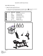
Locate and place front cap (#3) on the front of the unit as shown in Figure 7.
B.
Using a Phillips screwdriver, secure with two screws 8-16 x .50 (#11) and one screw
10-24 x .50 (#13).
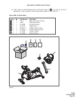
7. Connect the Seat Back Assembly.
A.
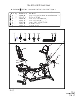
Locate the seat back assembly (#8) four screws 5-16-18 x 1.50 (#12) and four washers 5-16”
(#10).
B.
Place the seat back assembly in the correct position and hand thread each of the screws
5-16-18 x 1.50 (#12) and four washers 5-16” (#10). See Figure 8.
C.
Securely fasten the screws 5-16-18 x 1.50 (#12) with the 3/16” Allen wrench (#14) provided.
Cybex 530C and 530R Owner’s Manual
#12
Figure 8
#8
#10
#13
Figure 7
#11
#2
#9
#10
Figure 6
Base
Assembly
Setup
and Assembly
Page 5-11
Содержание 530C
Страница 2: ......
Страница 4: ......
Страница 10: ...Cybex 530C and 530R Owner s Manual This page intentionally left blank Page vi ...
Страница 24: ...Safety Page 1 14 Cybex 530C and 530R Owner s Manual This page intentionally left blank ...
Страница 26: ...Cybex 530C and 530R Owner s Manual Technical Specifications Page 2 2 This page intentionally left blank ...

