


1.4
Drive and brushless motor running - checklist
Below you can find a checklist with all the activities and operations needed to start up a new drive.
These operations are listed in the order they should be done. In further chapters you will also find
detailed description of the activities described below
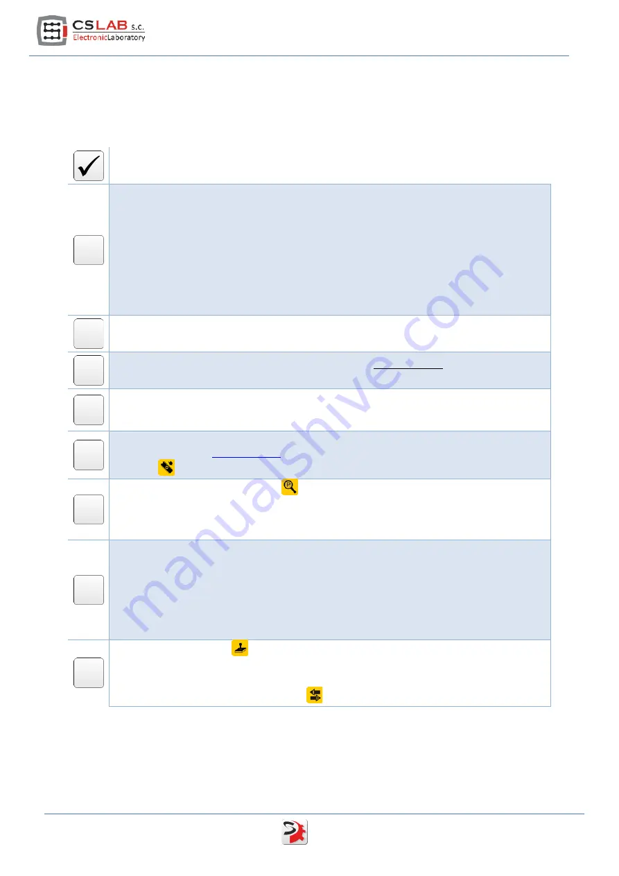
Operation name
Make necessary electrical connections:
•
Motor encoder
•
Motor Hall sensors
•
Phases: U, V, W and motor ground
•
I/O signals (Servo on / Reset / Alarm)
•
STEP/DIR control signals (STEP/DIR)
•
CAN bus
•
24V logic power supply (don't turn the power supply on yet!)
•
HV power output stage power supply (don't turn the power supply on yet!)
Install the csServoManager™ software and possibly the controller to the USB-RS232
converter (if you connect with the drive through RS232 port).
Turn on the 24V logic power supply, for the time being
do not turn on
the HV power output
stage power supply yet.
Now we are connecting with the drive. If you connect with the drive via CSMIO/IP controller
and you have more than one drive on the CAN bus then you have to set addresses for the
drives – read chapter 5.2.2 - „Connection through the CAN bus"
If the motor supplier is CS-Lab s.c. company load configuration template for the particular
) and save the configuration in non-volatile memory by
pressing
icon.
Open parameters monitor window
and select "Position (Encoder)" from the list. Turn a
motor shaft left and right. Counter should count alternately up and down, depending on
motor shaft rev direction. If the counter doesn't change the value or it skips only between -1
up to 1 then verify encoder connection.
In the parameters monitor window select "HALL sensors state" from the list. Turn the motor
shaft and watch indications. The sensors state should change in one of the following
sequences – depending on revs direction:
•
C__/CB_/_B_/_BA/__A/C_A/C__(etc.)
•
C__/C_A/__A/_BA/_B_/CB_/C__ (etc.)
If the sequence is incorrect or the state is „___” or „ABC” then verify HALL sensors
connection.
Open „JOG I/O control”
and verify I/O signals operation (for that you need to set the
necessary signals in CNC software – e.g. Mach3). It is good to test simDrive™ outputs by
setting the output on manual mode and clicking "set/clr" buttons. Change assignment of the
function to I/Os in configuration window
if necessary.
6
simDrive™ - AC Servo Drive User Guide
Содержание SimDrive M4-H040K
Страница 1: ...Applies to hardware version v1 Applies to firmware version v2 00 Rev 1 0 copyright 2014 CS Lab s c...
Страница 9: ...2 1 Brushless motors AC BLDC simDrive AC Servo Drive USER GUIDE 9...
Страница 10: ...2 2 Brushed motors DC 10 simDrive AC Servo Drive User Guide...
Страница 17: ...4 1 4 Digital inputs IN0 IN5 4 1 5 Digital outputs OUT0 OUT2 simDrive AC Servo Drive USER GUIDE 17...


