CS-Lab SimDrive M4-H040K Скачать руководство пользователя страница 27


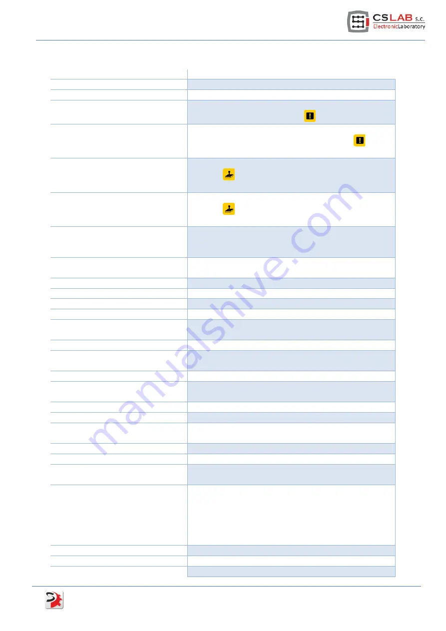
Here is a list of parameters which preview is available with their short description.  
 

PARAMETER NAME 

DESCRIPTION


Firmware version 

Drive firmware version 

Drive status 

Current drive state 

Alarm flags 

Alerts. Detailed alerts description in menu „Tools

Show 

Alerts” or after pressing  the icon 

 on the toolbar. 

Warning flags 

Warnings. Detailed alerts description in menu 
„Tools

Show Alerts” or after pressing  the icon 

 on the 

toolbar. 

Digital inputs  

Digital inputs state. You can see extended preview after 
pressing  

  on the toolbar or by selecting „Tools

JOG 

and I/O control” from the menu. 

Digital outputs 

Digital outputs state. You can see extended preview after 
pressing  

  on the toolbar or by selecting „Tools

JOG 

and I/O control” from the menu. 

External 5V output 

Current voltage value on pin 18 (encoder and Hall sensors 

power supply) of a signal connector. Correct value: 5V +/-

10% 

24V power supply 

Current value of logic power supply. Correct value: 24V +/-

10% 

Power stage temperature 

Power output stage temperature (

O

C) 

Torque scan state  

Current state of torque scanner (function csTorqueScan™) 

Autotuner state 

Current state of PID regulators autotuning function.  

Autotuner tuning state 

Current stage of PID regulators tuning. 

Planner idle flag 

„1” value means that internal motion planner in a drive 

finished operation and is in idle state.  

Encoder position 

Encoder position counter 

Reference position 

Controller position counter that is counter directly 

connected with STEP/DIR signal. 

Encoder velocity 

The speed is counted on a motor's encoder 

Reference velocity 

The speed is counted on STEP/DIR control signal (converted 

from frequency to revs/min) 

Reference acceleration 

The acceleration is counted on STEP/DIR control signal 

STEP frequency 

STEP signal frequency 

Following error 

Current deviation from the target position in encoder 

pulses. 

Following error (Max) 

Max. temporary deviation from target position. 

Velocity error 

Current deviation from target speed. 

Velocity error (Max) 

Max. temporary deviation from target speed that results 

from measured STEP signal frequency  

Encoder errors 

Encoder faulty readouts number. This value should be „0”. 

If the value is higher than zero then it means wiring 

problems or encoder failure.  Encoder failure is very rare; 

usually it's poor quality wiring or no contact of one of 

encoder signal. Value higher than zero also means that 

positioning errors will appear.  

Mechanical angle (encoder) 

Mechanical angle of motor rotor defined by an encoder 

Electrical angle (encoder) 

Electronic angle of motor rotor defined by encoder 

Electrical angle (HALL) 

(Brushless motors only). Electrical angle of motor rotor 

 simDrive™ AC Servo Drive - 

U

SER 

G

UIDE


  27 

Содержание SimDrive M4-H040K

Страница 1: ...Applies to hardware version v1 Applies to firmware version v2 00 Rev 1 0 copyright 2014 CS Lab s c...

Страница 2: ...onfiguration connector model M4 040K 15 4 I O circuits internal construction 16 4 1 1 Encoder inputs 16 4 1 2 HALL sensors inputs 16 4 1 3 STEP DIR control signals inputs 16 4 1 4 Digital inputs IN0 I...

Страница 3: ...r tuning 35 5 6 1 Initial settings of PID regulator 35 5 6 2 Manual PID regulator tuning procedure 36 5 6 3 Automatic PID regulator tuning procedure 39 5 7 Torque scan function csTorqueScan 41 6 Drive...

Страница 4: ...e speed electrical power drive systems Safety requirements Electrical thermal and energy EN 61800 3 Adjustable speed electrical power drives systems EMC requirements and specific test methods EN 61000...

Страница 5: ...gnal type of position speed defining STEP DIR Differential signal Max STEP signal frequency 4 MHz Max encoder signal frequency 8 MHz Encoder type incremental TTL 4 Encoder signal type Differential PC...

Страница 6: ...rives read chapter 5 2 2 Connection through the CAN bus If the motor supplier is CS Lab s c company load configuration template for the particular model available on www cs lab eu and save the configu...

Страница 7: ...ch it on and connect with the drive Open PID regulators tuning window and ensure that the needed values in there are safe for the first run look at chapter 5 6 1 Initial settings of PID regulator Enab...

Страница 8: ...er is also optional but we recommend Alarm Reset Servo ON and E Stop signals connection The drive has HOME signal and encoder index synchronization function It means that you can have precise homing e...

Страница 9: ...2 1 Brushless motors AC BLDC simDrive AC Servo Drive USER GUIDE 9...

Страница 10: ...2 2 Brushed motors DC 10 simDrive AC Servo Drive User Guide...

Страница 11: ...040K model 3 2 Connectors arrangement M4 075K model CN1 Signal connector CN5 CAN and configuration CN1 Signal connector CN3 Power output stage connector CN2 Configuration connector CN3 power output st...

Страница 12: ...B Input 17 HALL_C HALL sensor C Input 18 5V Out 5V Output for encoder and HALL sensors power supply 19 GND GND 0V of encoder and HALL sensors 20 GND GND 0V of logic power supply 21 STEP Step signal ne...

Страница 13: ...d outputs there are default functions assigned in square brackets The sign means that input output in reversed logic that is 0V is an active state and 24V is inactive state Connection made in accordan...

Страница 14: ...N bus housing Shield Wire shielding PIN number Signal Description 1 HV Power supply of power output stage 2 HV Power supply of power output stage 3 PE Ground 4 W Motor power supply W phase 5 V Motor p...

Страница 15: ...Description 1 2 RxD RS232 diagnostics and configuration 3 TxD RS232 diagnostics and configuration 4 CAN H CAN bus H signal 5 GND GND 0V 6 7 8 9 CAN L CAN bus L signal housing Shield Wire shielding Fro...

Страница 16: ...4 I O circuits internal construction 4 1 1 Encoder inputs 4 1 2 HALL sensors inputs 4 1 3 STEP DIR control signals inputs 16 simDrive AC Servo Drive User Guide...

Страница 17: ...4 1 4 Digital inputs IN0 IN5 4 1 5 Digital outputs OUT0 OUT2 simDrive AC Servo Drive USER GUIDE 17...

Страница 18: ...erienced users will be able to set the simDrive device properly To configure the drive we need csServoManager configuration utility available free on http www cs Lab eu while a converter and a cable c...

Страница 19: ...finishes you can click on windows start menu and find simDrive Software Package Install USB Serial Converter After driver installer launching you should follow the screen information After a short tim...

Страница 20: ...onnection with a drive After we start the csServoManager we will see a window where we choose a drive to connect with and interface language as well First click Scan button You will see all detected d...

Страница 21: ...on menu click Communication and change the address into 105 o Save the configuration in non volatile memory Configuration Save in flash memory o End the connection the first icon on the left on a tool...

Страница 22: ...Save Parameters Save settings to a file Configuration Save to flash memory IMPORTANT Settings file save in non volatile memory You should click the icon after you make changed the drive s configurati...

Страница 23: ...window for PID regulators tuning Configuration Motor parameters Motor parameters settings Configuration IO Signals Drive s digital inputs and outputs configuration Tests window It s not used in normal...

Страница 24: ...rter CSMIO IP CAN Connection through LAN network a PC communicates via CSMIO IP controller in this case CAN bus drive connection with CSMIO IP controller is required 5 2 4 3 Port Sign Description COMx...

Страница 25: ...le memory Changes made in the drive configuration will be lost after power supply disconnection if we don t press the icon on our toolbar or Save in flash memory in Settings menu Sometimes we do not w...

Страница 26: ...t refresh frequency Auto scale automatic manual scale of the chart Y axis Max Min min max values settings for Y axis if manual scale of Y axis is enabled Under the chart control group there are curren...

Страница 27: ...value means that internal motion planner in a drive finished operation and is in idle state Encoder position Encoder position counter Reference position Controller position counter that is counter dir...

Страница 28: ...r id current Brushed motors d vector current Its values should be close to 0 Vector iq current Current consumed by a motor that provides a torque id Vector reg error Current id vector adjustment devia...

Страница 29: ...here are different types of brushless motors AC Generally we differentiate two types of them synchronous with permanent magnets and asynchronous simDrive servo drive just like most other servo drives...

Страница 30: ...not have to enter it With future software versions the parameter can be important for sensorless methods of determining an angle of a rotor a motor commutation L Motor winding resistance In current so...

Страница 31: ...we enter here should be actual resolution manufacturers usually inform about of the value because they don t include a quadrature decoder Incorrect value won t cause the motor damage but it won t be...

Страница 32: ...tion is expressed by the formula In our example we enter X 20 and Y 1 We are going to multiply the input signal by 20 Obviously using this function we can divide the input signal if there is such a ne...

Страница 33: ...on option It s good to clear all current settings first before the configuration For inputs we select 0 input and we click on 5 input while holding Shift key at the same time Click on all this way sel...

Страница 34: ...nputs in csServoManager Digital input number Default function Default polarization 0 Homing input Reversed 1 Servo ON Normal 2 Reset Normal 3 4 5 5 5 3 Digital outputs functions Function Description A...

Страница 35: ...menu Configuration PID tuning or click on the icon on the toolbar 5 6 1 Initial settings of PID regulator Optimal initial values for various motor types may differ significantly however in the table...

Страница 36: ...Due to very small accelerations the motion can be a bit ponderous and unequal but it s normal o When you hear squeaks or you get an overload or short circuit alarm you should decrease PID current con...

Страница 37: ...lowly by 25 If we get an alarm state during the current controller tuning then you should decrease the gain value by 25 and press Reset and again o We tune the Ki parameter of current controller the s...

Страница 38: ...of velocity controller as well To keep the changes saved after power supply is off press icon on a toolbar after you done the changes or select Save to flash from Configuration menu Remember to appro...

Страница 39: ...to tune the PID manually Autotuning function is available in a PID tuning window and to open it click Configuration PID tuning from a menu or click icon on the toolbar and go to Autotuning tab Usuall...

Страница 40: ...so oscillations are more likely to happen Less rigidity the positioning is worst but oscillations are less likely to happen The autotuning procedure requires a motor to be in motion and mechanically m...

Страница 41: ...earlier Make sure that power outputs stage power supply HV is enable and a drive is ready if it is in alarm state scanning won t start Set Ampl Slider to 1 value and Phase to 0 Click Scan button and w...

Страница 42: ...ration of csTorqueScan function constant mechanical load is required If a machine mechanics doesn t assure that for example an axis drive is on a straight tooth bar the measurement should be done on a...

Страница 43: ...persists then you assure better cooling for the driver and a control cabinet Following error velocity controller Rotational speed of a motor differs too much from the set speed It means to high revs o...

Страница 44: ...ad out error default settings loaded CRC32 control value in device memory was incompatible and default settings were loaded It means drive s settings loss and or non volatile memory of a device malfun...

Страница 45: ...lows 1 Make sure that simDrive servo driver is connected through RS232 COM port updates through CAN bus is not supported 2 Select your language and press Start 3 Wait until the uploader will detect th...

Страница 46: ...ows down moreover we are already nervous and we overreact stepping on the gas or brake to the limit time and time again As a result we will still pass the chased car being most of the time far away fr...

Страница 47: ...ry Motor position 1 Error 0 1 1 The output 10 1 10 Motor position 5 Error 0 5 5 The output 10 5 50 Motor position 5 Error 0 5 5 The output 10 5 50 As you can see above correction is greater the larger...

Страница 48: ...ts sudden rapid movements The D reacts the stronger the faster a position error changes If the error increases fast the D control will react towards strongly If the error decreases quickly then the D...

Страница 49: ...pt so when we want to mill a square we get a diamond shape There is no way to correct these inaccuracies as after we switch the power on the gantry s both side drives are like stuck together In a syst...

Страница 50: ...r position counter Following error Motor load current absorbed by a motor Hall sensors state Drive state Digital inputs and outputs state Power output stage temperature Alarms shown as easy control le...

Отзывы: