background image


47 

3.4.4


CANBUS 

battery chargers have two terminals made for connectors Molex Microfit 3.0, 6 circuits (reference 43045-

0600). 
Documentation n° 

1336205REG_CAN

 (hardware and software specification) is available upon request. 

 
Protocol 
CAN-Bus protocol can be chosen with the programming field 3 (see 3.3.4)
 
Power Supply 
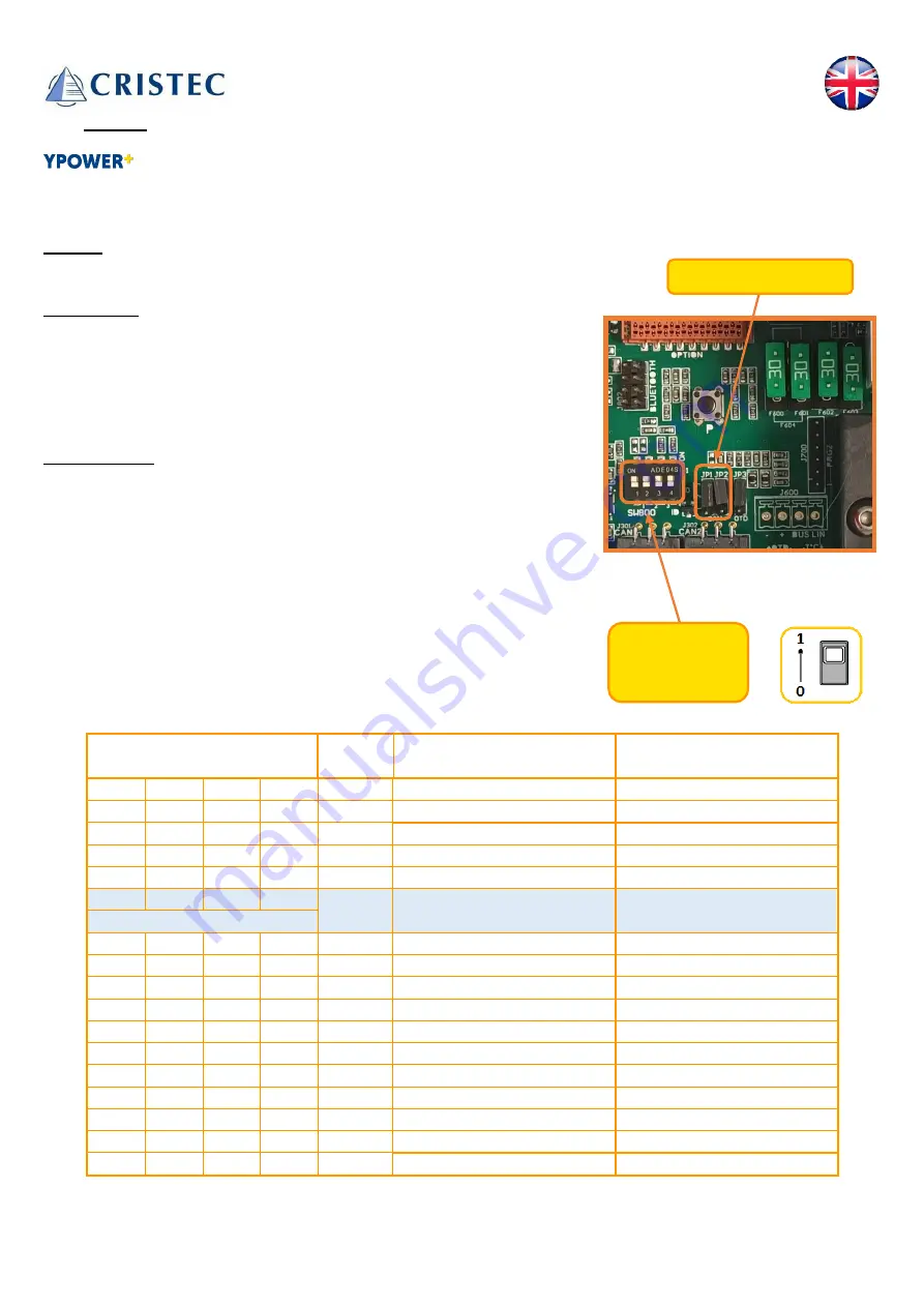
The power supply of the CAN-Bus can either be carried out by another 
equipment or by the charger itself. 
 
To generate the power supply, simply move the two jumpers JP1 and JP2 to 
position 1-2. 


Communication 
To allow communication between multiple devices, each entity must have a 
unique identifier (ID). This identifier must be selected using the 4 micro 
switches (1,2,3,4). 
 
Within the same CAN network, 4 sub-networks can be defined (A, B, C, D). 
Thus, only the 4 entities of the sub-networks can communicate with each other. 


Switches settings  

ID 

Master/Slave 

function 

Sub-network 

N° 


0  

Master A 

Master B 

Master C 

Master D 

Slave A1 

Factory settings 

Slave B1 

Slave C1 

Slave D1 

Slave A2 

Slave B2 

10 

Slave C2 

11 

Slave D2 

12 

Slave A3 

13 

Slave B3 

14 

Slave C3 

15 

Slave D3 

Jumpers JP1 et JP2 


Dip switches :            

(1, 2, 3, 4) 

Содержание UEYPOPL/12-4Q/3D

Страница 1: ...Manuel utilisateur de l unité d énergie _ Modèles 12V 40A et 12V 60A S A S CRISTEC 31 rue Marcel Paul Z I Kerdroniou Est 29000 QUIMPER FRANCE E mail info cristec fr https www cristec fr UEYPOPL A A ...

Страница 2: ...1 Manuel d utilisation en Français 2 User Manual in English 29 UEYPO _1 ...

Страница 3: ...E L UNITE D ENERGIE 16 3 3 1 REGLAGE PAR BOUTON POUSSOIR 16 3 3 2 CHAMP DE PROGRAMMATION 1 MODIFIER LE TYPE DE BATTERIE 18 3 3 3 CHAMP DE PROGRAMMATION 2 MODIFIER UN MODE SPECIFIQUE 18 3 3 4 CHAMP DE PROGRAMMATION 3 SELECTION DE PROTOCOLE BUS CAN 19 3 4 OPTIONS ET FONCTIONNALITES 19 3 4 1 BLUETOOTH 19 3 4 2 COMPENSATION EN TEMPERATURE EN OPTION 19 3 4 3 CAPTEUR OTD EN OPTION 19 3 4 4 BUS CAN 20 3 ...

Страница 4: ...cument s appliquent au produit qui l accompagne La société se réserve le droit d en modifier les spécifications sans préavis 1 1 PRECAUTIONS MISE EN GARDE DISPOSITIONS RELATIVES A LA SECURITE Matériel de classe I selon la norme NF EN 60335 2 29 Les prescriptions d installation sont contenues dans la norme NFC 15 100 et aux normes spécifiques petits navires systèmes électriques installations à cour...

Страница 5: ...tions relatives à l utilisation de l appareil en toute sécurité leur ont été données et si les risques encourus ont été appréhendés alors ils ou elles pourront l utiliser sous la surveillance d une personne responsable Les enfants ne doivent pas jouer avec l appareil ...

Страница 6: ...t être impérativement raccordé à la terre de l installation Il doit être raccordé avant toutes les autres bornes voir 3 2 2 L unité d énergie doit être fermée avant toute mise sous tension le capot doit être relié au châssis de l unité d énergie par le câble et la cosse prévus à cet effet Sauf pour le paramétrage de l unité d énergie voir 3 3 1 Courant de fuite accidentel entre circuit DC et masse...

Страница 7: ... une paroi verticale selon les indications fournies dans ce manuel Il est impératif de conserver une zone de 150mm autour de l unité d énergie L installateur prendra les dispositions nécessaires pour que la température d air à l entrée soit inférieure à 65 C dans les conditions extrêmes de fonctionnement Les dispositions nécessaires seront également prises pour permettre un dégagement de l air cha...

Страница 8: ...euvent générer une dégradation irréversible du matériel et un danger potentiel pour l utilisateur L appareil doit être positionné dans un endroit sec et bien ventilé Dispositions vis à vis des matériels inflammables L unité ne doit pas être utilisée à proximité de matériels liquides ou gaz inflammables Les batteries sont susceptibles d émettre des gaz explosifs pour l installation des batteries pr...

Страница 9: ...r section 5 3 Fabricant Bussmann EATON Référence ATM 20 ATM30 ATM15 Autres dispositions Ne pas percer ou usiner le coffret de l unité d énergie risque de casse de composants ou de projection de copeaux ou limailles sur la carte de l unité d énergie Tout ce qui n est pas stipulé dans ce manuel est rigoureusement interdit ...

Страница 10: ...ntage remontage et tests ainsi que tous les autres frais non cités Notre garantie ne peut en aucun cas donner lieu à une indemnité CRISTEC ne peut être tenu pour responsable des dommages dus à l utilisation de l unité d énergie La garantie ne s applique pas si l origine de la défaillance est due à un défaut d origine externe voir ci dessous Dans cette hypothèse un devis de réparation sera émis Not...

Страница 11: ...ue régulée et filtrée Ils peuvent fonctionner en chargeur de batteries et en alimentation à courant continu Le fonctionnement de l unité d énergie est entièrement automatique après sélection préalable du type de batterie et du type de charge Elle peut rester raccordée de façon permanente aux batteries sauf stipulation contraire du fournisseur ou fabricant de batteries et ne nécessite pas d être dé...

Страница 12: ...11 Passe câbles Sorties AC 2 3 DIAGRAMME FONCTIONNEL CONNECTIQUE Bornier à vis Sorties DC Presse étoupe Entrée AC Liaison équipotentielle terre DC côté dissipateur ...

Страница 13: ...1 ENCOMBREMENT ET POIDS DE L UNITE D ENERGIE La fixation de l unité d énergie se fait par 4 vis M5 tête ronde 3 2 CABLAGE Il est impératif de ne pas installer le dispositif sous tension Toute source d énergie doit être éteinte Les batteries doivent être isolées par les coupe batteries selon la norme en vigueur Les chargeurs alternateurs ou autres dispositifs générant de l énergie doivent être étei...

Страница 14: ...on de test du disjoncteur différentiel ne fonctionne pas pour des tensions inférieures à 185VAC 1 Consulter CRISTEC pour toute utilisation en 115VCA 60Hz Groupes électrogènes Les unités d énergie CRISTEC sont conçues pour fonctionner sur groupe électrogène Attention Dans certains cas les groupes électrogènes peuvent générer des surtensions importantes en particulier dans leur phase de démarrage Av...

Страница 15: ...Remarque Les chargeurs des unités d énergie sont en fonctionnement dès lors qu ils sont sous tension câble de réseau AC d entrée connecté et alimenté Les chargeurs des unités d énergie sont à l arrêt dès qu ils ne sont plus sous tension AC délai d extinction de 10 minutes et que le réseau DC de sortie est déconnecté pour un mode STANDBY activé dès qu ils ne sont plus sous tension AC délai d extinc...

Страница 16: ...ligatoirement de section choisie entre les valeurs indiquées dans le tableau ci dessous Modèle Section minimale des câbles DC Section maximale des câbles DC 12 40 16 mm 16 mm 12 60 35 mm 35 mm Le type de câble H07 VK MX etc devra être défini par l installateur en fonction du type d application et des normes applicables 3 2 5 Câble de liaison équipotentielle à la terre de l installation à courant c...

Страница 17: ...s éteint vous pouvez alors ouvrir le capot métallique sans risque électrique Vous avez 10 minutes pour faire le réglage et remettre le tout sous tension La visualisation des LED se fait sur la carte mère de l unité d énergie Les chargeurs sont équipés d un bouton de paramétrage P permettant de configurer le chargeur notamment le type de batteries voir paragraphe 3 3 2 Pour passer en mode de progra...

Страница 18: ...reprendre la charge Réglage 1 Réglage 2 Réglage n Appuyez sur le bouton P Appuyez sur le bouton P Appuyez sur le bouton P Champ 2 Réglage 1 Réglage 2 Réglage n Appuyez sur le bouton P Appuyez sur le bouton P Appuyez sur le bouton P Champ 3 Réglage 1 Réglage 2 Réglage n Appuyez sur le bouton P Appuyez sur le bouton P Appuyez sur le bouton P DEROULEMENT DE LA PROGRAMMATION NB au démarrage de l unité...

Страница 19: ...er phosphate LiFePO4 avec BMS 13 8V 14 4V 6H 1H 10 Bat STORMLINE 13 7V 14 5V 2H 6H 11 Réservé 12 0V 12 0V 0H 0H 12 Réservé 12 0V 12 0V 0H 0H 13 OFF Programmation par Bluetooth 14 OFF Programmation Bus CAN 15 OFF Réservé Tension sur BAT avec 10 du courant nominal avec une tolérance de 1 Le REFRESH est déconseillé pour certains types de batteries AGM Système de supervision de la batterie Des réglage...

Страница 20: ...d Absorption et de la tension de Floating en fonction de la température ambiante du local batteries Le coefficient adopté est de 18mV C Les sondes sont disponibles en option La compensation en température n est pas appliquée pour les courbes Hivernage Alimentation stabilisée ou lithium fer phosphate LiFePO4 avec BMS 3 4 3 Capteur OTD en option Les chargeurs sont équipés d une entrée capteur OTD di...

Страница 21: ...ation entre plusieurs équipements chaque entité doit posséder un identifiant unique ID Cet identifiant doit être sélectionné à l aide des 4 micros interrupteurs 1 2 3 4 Au sein d un même réseau CAN on peut définir 4 sous réseaux A B C D Ainsi seules les 4 entités des sous réseaux peuvent communiquer entre elles Réglage des switches ID Position Maître Esclave Bus CAN uniquement Sous réseau 1 2 3 4 ...

Страница 22: ...ion de courant en sortie Ce mode ne peut s activer que par l application Bluetooth ou le BUS CAN Le chargeur a une limitation du courant de sortie ainsi le chargeur pourra délivrer une portion de courant nominal définie par l utilisateur 3 4 7 Réglages usine Le chargeur est configuré en sortie d usine type batterie plomb étanche BOOST ON REFRESH OFF STANDBY ON 600 secondes Cette configuration est ...

Страница 23: ... l unité d énergie si la batterie est déchargée Le courant est alors maximum Phase ABSORPTION Commence dès que la tension a atteint la valeur maximale du BOOST Le courant commence à décroître Ces deux phases cumulées durent au maximum TBOOST TABS suivant configuration Si le courant atteint une valeur inférieure à 20 du courant nominal la phase FLOATING s enclenche automatiquement La durée et le co...

Страница 24: ...ON et FLOATING si des consommations DC constantes sont détectées l unité d énergie redémarre un nouveau cycle de charge complet comprenant une phase de BOOST Cette phase de REBOOST est autorisée après une mesure d une certaine tension de batterie pendant une durée déterminée BOOST en position OFF Dans cette configuration l unité d énergie délivre une courbe de charge de type mono palier IU Elle gé...

Страница 25: ...ux LED clignotent en bleu trois fois Led Mode Etat des LED Etat de l unité d énergie LED 1 ON En charge Chargeur sous tension Mode stand by voir section 3 4 5 Programm ation Mode programmation voir section 3 3 Défaut éteint Absence ou dégradation du réseau alternatif Rupture fusible entrée Dysfonctionnement interne de l unité d énergie LED 2 PHASE DE CHARGE Normal Chargeur en phase BOOST Chargeur ...

Страница 26: ...les dépôts de poussière pouvant altérer l évacuation de la chaleur Vérifier l état de charge des batteries tous les 3 mois Une vérification annuelle du serrage des écrous et vis est nécessaire pour garantir le bon fonctionnement de l appareil particulièrement en milieu perturbé vibrations chocs écarts de température importants etc 4 3 REPARATION DES EQUIPEMENTS Déconnecter l unité d énergie du rés...

Страница 27: ...s de fixation 180x 133 mm Vis de fixation murale 4 vis M5 tête ronde Indice de protection IP20 Normes Marquage CE CEM NF EN61000 6 1 NF EN61000 6 2 Marquage CE sécurité NF EN60950 5 2 DISTRIBUTION AC Modèle 12V 40A 12V 60A Entrée Tension 115 1 230 15 monophasé Fréquence 50 60Hz 1 Intensité 16A selon consommation de sortie Disjoncteur d entrée Disjoncteur différentiel bipolaire 16A ou 32A selon mod...

Страница 28: ...ée et filtrée Voir 3 3 2 Ondulation et bruit crête à crête 2 aux conditions nominales Fusible automobile monté en série dans le pôle BAT 3 x 30A 32V F400 F401 F402 4 x 30A 32V F400 F401 F402 F403 Protections électriques Contre les surtensions d entrée transitoires par varistance hors garantie Contre les inversions de polarité en sortie par fusible Contre les courts circuits et les surcharges en so...

Страница 29: ...T INDICATORS 43 3 3 1 SETTING WITH PUSH BUTTON 43 3 3 2 PROGRAMMING FIELD 1 SELECT BATTERY TYPE 45 3 3 3 PROGRAMMING FIELD 2 MODIFY BOOST AND REFRESH MODES 45 3 3 4 PROGRAMMING FIELD 3 CAN BUS PROTOCOLS 46 3 4 OPTIONS AND FEATURES 46 3 4 1 BLUETOOTH 46 3 4 2 THERMAL COMPENSATION OPTIONAL 46 3 4 3 OTD SENSOR OPTIONAL 46 3 4 4 CANBUS 47 3 4 5 STANDBY MODE 48 3 4 6 OUTPUT CURRENT LIMITATION 48 3 4 7 ...

Страница 30: ...ing product CRISTEC reserves the right to modify the specifications without notice 1 1 PRECAUTIONS WARNING PROVISIONS RELATING TO SAFETY Material class I according to NF EN 60335 2 29 standards The requirements for installation are contained in the NFC 15 100 standards and in the specific standard for small crafts electrical systems Alternating and direct current installations ISO13297 reference T...

Страница 31: ...31 supervision or instruction concerning use of the appliance by a person responsible for their safety Children should be supervised to ensure that they do not play with the appliance ...

Страница 32: ...rotection Earth Terminal PE must be earthed and connected before any other terminal see 3 2 2 The shore power unit must be sealed before any power up the cover must be connected to the frame of the shore power unit by the cable and the terminal provided for this purpose exept for the setting with the push button see 3 3 1 Accidental leakage current between the charge circuit and the earth accident...

Страница 33: ...tition as indicated herein It is imperative that there be a gap of 150mm around the shore power unit The installer must ensure that the temperature of the air at the input is lower than 65 C in extreme operating conditions Measures should also be taken to allow evacuation of hot air on either side of the shore power unit It s strictly forbidden to put any device on or against the shore power unit ...

Страница 34: ...ll ventilated place Precautions regarding inflammable materials The shore power unit should not be used near inflammable materials liquids or gases The batteries can emit explosive gases please follow the manufacturer s instructions carefully when installing them Nearby the batteries ventilate the area do not smoke do not use any open flame Fuses DC output fuses should only be replaced with the ap...

Страница 35: ...ons Never attempt to drill or to machine the shore power unit s case this may damage components or cause metal chips or filings to fall on the unit s board Do not do anything that is not explicitly stated in this manual ...

Страница 36: ...reassembly and testing costs as well as all other costs not mentioned Our warranty on no account provides for any form of compensation CRISTEC shall not be held liable for damage incurred as a result of using the charger The warranty does not apply if the origin of the failure is due to an external default see below In this case a repair estimate will be issued Our warranty does not cover 1 Non co...

Страница 37: ...e as a battery charger and as a DC power supply The operation of the shore power unit is fully automatic after a selection of the type of battery and the type of charge It can remain connected to the batteries unless otherwise stipulated by the battery supplier or manufacturer and does not need to be disconnected when starting the engine marine application because because it is equipped with an in...

Страница 38: ...38 Grommets AC outputs 2 3 FUNCTIONAL DIAGRAM CONNEXIONS screw terminal block DC outputs Cable gland AC input Protection earth coonnector back view ...

Страница 39: ... POWER UNIT SIZE AND WEIGHT The shore power unit is fixed using 4 round head M5 screws 3 2 WIRING It is essential not to install the device under voltage All energy sources must be turned off The batteries must be isolated by the battery switches according to the standard in force Chargers alternators or other energy generating devices must be turned off otherwise isolated The references of the ad...

Страница 40: ...tion standards NOTE The residual current device test button does not work for voltages below 185VAC 1 Consult CRISTEC for any use at 115VAC 60Hz Generators CRISTEC shore power units are designed to operate from a generator Be careful In some cases the generators can produce high over voltages in particular during start up phase Before connecting the charger please check its compatibility with the ...

Страница 41: ...ne and Neutral respectively on screw terminals 2 and 4 Remarks The chargers are working as soon as they are powered on AC cable connected and powered The chargers are stopped as soon as they are no longer under AC voltage power off delay of 20 seconds and the output DC network is disconnected for an activated standby mode as soon as they are no longer under AC voltage power off delay of 20 seconds...

Страница 42: ...le cross section Maximum allowable battery cable cross section 12 40 16 mm 16 mm 12 60 35 mm 35 mm The installer should choose the type of cable H07 VK MX etc according to the type of application and the applicable standards 3 2 5DC Equipotential bonding cable to the ground An equipotential wire for DC must be installed between the metal casing of the shore power unit and the negative terminal of ...

Страница 43: ...minutes to make the setup and turn everything back on The visualization of the each state of the charger is visible on the LEDs on the motherboard of the energy unit The battery chargers are equipped with a push button to configure the battery charger according to the battery type see chapter 3 3 2 and other features To switch to programming mode press Push button during 1 sec The ON LED LED 1 wil...

Страница 44: ... than 1 sec to go to Next Field Press Push button P More than 1 sec to go to Next Field Press Push button P More than 1 sec to save the configuration Charger working Programming Field 1 Short Push on P Short Push on P Programming Field 2 Value 1 Value 2 Value n Short Push on P Short Push on P SETTING THE CHARGER NB At start up the number of flashes of charging phase led shows which curves is appli...

Страница 45: ...H 4H 9 Lithium iron phosphate LiFePO4 with BMS 13 8V 14 4V 6H 1H 10 STORMLINE Bat 13 7V 14 5V 2H 6H 11 Specific 12 0V 12 0V 0H 0H 12 Specific 12 0V 12 0V 0H 0H 13 Customizable with Bluetooth 14 Customizable with CAN Bus 15 Unused Some specific settings are possible please consult us Voltage on BAT1 BAT2 BAT3 and BATE with 10 of the rated current and a tolerance of 1 REFRESH is not advised for cert...

Страница 46: ...nsation of Absorption voltage and Floating voltage depending on the ambient temperature of the battery room The coefficient used is 18mV C for 12V models Temperature is not compensated when Wintering or standby sealed bat Stabilized DC power supply or Lithium iron phosphate LiFePO4 with BMS settings are selected 3 4 3 OTD sensor Optional chargers are equipped with an OTD over temperature protectio...

Страница 47: ...en multiple devices each entity must have a unique identifier ID This identifier must be selected using the 4 micro switches 1 2 3 4 Within the same CAN network 4 sub networks can be defined A B C D Thus only the 4 entities of the sub networks can communicate with each other Switches settings ID Master Slave function Sub network 1 2 3 4 N 0 0 0 0 0 Master A A 1 0 0 0 1 Master B B 0 1 0 0 2 Master ...

Страница 48: ...imitation This mode can only be activated by the Bluetooth application or the CAN Bus The charger has an output current limitation so the charger will be able to deliver a percentage of the nominal current defined by the user 3 4 7Factory settings The charger s factory settings are sealed lead BOOST ON REFRESH OFF STANDBY OFF This setting is a compromise for satisfactory recharging of different te...

Страница 49: ...the charger is turned on if the battery is flat The current is then at maximum output ABSORPTION phase Begins when the voltage has reached the maximum BOOST level The current level starts falling These two phases combined last a maximum of TBOOST TABS depending on setting If the current falls below 20 of rated current the FLOATING phase automatically kicks in Duration and current intensity depend ...

Страница 50: ...OOST ABSORPTION and FLOATING if some DC constant consumptions are detected the charger will restart a new complete charge cycle including a BOOST phase This REBOOST phase will be authorized after measuring certain battery voltage during a determined time BOOST in OFF position With this setting the charger produces a single stage UI type charge curve It generates a constant voltage supplying the cu...

Страница 51: ...tatus LED 1 ON Charging Charger is ON Stand by mode see section Erreur Source du renvoi introuvable Programming Programming see section 3 3 Fault off No or poor quality AC current Input fuse is blown Internal charger malfunction LED 2 CHARGING PHASE Charging Charger in BOOST phase Charger in ABSORPTION phase Charger in FLOATING phase Charger in REFRESH phase off Output voltage OFF Fault Other faul...

Страница 52: ...ust deposits may adversely affect heat dissipation Check the state of battery charge every 3 months Nuts and screws should be tightened annually to ensure efficient operation of the appliance particularly in rugged conditions vibrations shocks high variations in temperature etc 4 3 EQUIPEMENT REPAIRS Disconnect the battery charger from the AC power network and disconnect the batteries before under...

Страница 53: ...xing screw wall 4 x M5 round head screws Protection factor IP20 Standards CE CEM MARK NF EN61000 6 1 NF EN61000 6 2 CE security MARK NF EN60950 5 2 AC DISTRIBUTION Part Number 12V 40A 12V 60A Input Voltage 115 1 230 15 single phase Frequency 50 60Hz 1 Current 16A depending on output consumption Input protection 16A or 32A bipolar RCD depending on model Output Voltage 115 1 230 15 single phase Freq...

Страница 54: ...t voltage See 3 3 2 Peak to peak ripple and noise 2 at rated conditions Automotive output fuse mounted in series in minus pole BAT 3 x 30A 32V F400 F401 F402 4 x 30A 32V F400 F401 F402 F403 Protections Against transient input overvoltage by varistor out of warranty Against output polarity inversions by fuse replaceable automotive type Against short circuits and output overloads Against abnormal ov...

Отзывы: