13 - ENG
D20396
NOTE
This is the only time you should operate
your compressor with the belt guard
removed. Use caution when checking
engine speed.
High engine speeds greatly increase
vibration loads on air tank. This could
weaken the tank and cause it to rupture or
explode. Damage to the engine can also
occur. Engine RPM must be set per specifi-
cation.
2.
Measure engine speed with belt removed using a
tachometer. Speed should be as follows:
No-Load (Max)
Compressor Model No. Speed ( 100 RPM)
919.157251
3700 RPM
If speed is correct go to Step 5.
3.
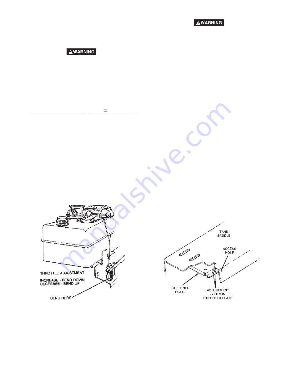
Four bolts fasten the engine to tank base. Position
yourself on the starter rope side of engine and locate
that engine mounting bolt nearest you on the left. In
this area, there is one vertical spring. Locate the
vertical spring situated directly above the mounting
bolt just described.
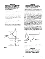
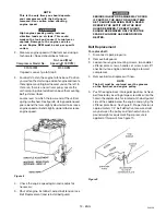
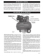
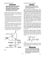
Locate lever to which the lower end of the vertical
spring is attached. See figure 8. Using needle nosed
pliers, bend the lever slightly downward to increase
engine speed or bend slightly upward to decrease
engine speed.
4.
Check the engine speed again and readjust as
necessary.
5.
Shut off engine, install belt, adjust belt tension (see
Belt Replacement) and reinstall belt guard.
Figure 8
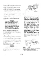
SERIOUS INJURY OR DAMAGE MAY OCCUR
IF PARTS OF THE BODY OR LOOSE ITEMS
GET CAUGHT IN MOVING PARTS. NEVER
OPERATE THE OUTFIT WITH THE BELT
GUARD REMOVED. THE BELT GUARD
SHOULD BE REMOVED ONLY AFTER THE
SPARK PLUG WIRE HAS BEEN DISCON-
NECTED.
Belt Replacement
To replace belt:
1.
Disconnect spark plug wire.
2.
Remove belt guard.
3.
Loosen four engine mounting screws, two saddle/
stiffener plate screws, handle set screw, and stiff
ener bar nut on engine and slide engine toward
compressor.
4.
Remove belt and replace with new.
NOTE
The belt must be centered over the grooves
on the flywheel and engine pulley.
5.
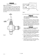
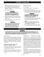
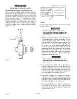
Push the engine back into regular position. Achieve
belt tension by inserting a large screwdriver into the
hole in the saddle which is located on the belt guard
side of the saddle below the engine and prying the
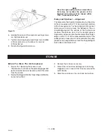
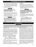
stiffener plate back. See figure 9. Proper tension is
approximately 1/4" belt deflection measured mid
way between the pulley and flywheel when a 3-
pound weight or equivalent finger pressure is
applied at this point. See figure 10.
Figure 9

