background image

37

FLUE

OPTIONS 

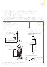
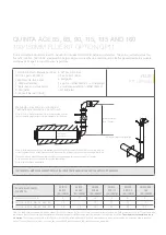
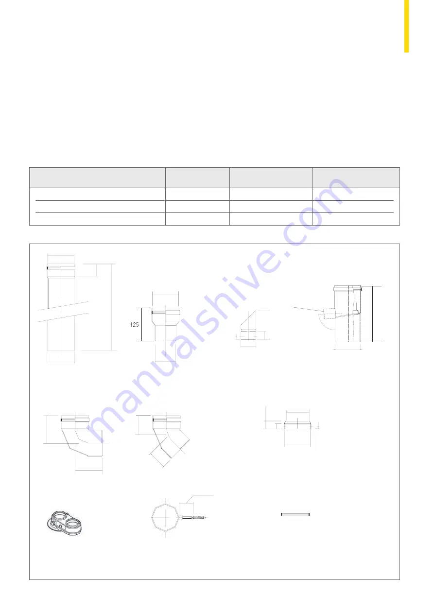
QUINTA ACE 30 AND 45


100MM CONVENTIONAL OR OPEN-FLUE SYSTEMS

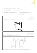
The components listed below are only suitable for internal use as illustrated on pages 33 and 34. As the boiler  
is fan assisted it makes no difference if the run is horizontal or vertical but the flue should terminate vertically.

Calculation data based on flue products supplied by Remeha. Other distances available at 110mm (see manual) are achievable with increased flue sizes. 

Note:  All dimensions are in mm. 
Note 2: Fall to boiler ≥ 50mm/Mtr.

15mm ID/32mmO/D

100mm

180mm

101 i/d

100 o/d

50

'L'

101 i/d

80 o/d

101 i/d

10

60

200

Top

76

76

105

105

30

20

10

101 i/d

95

25-55mm

15mm ID/32mmO/D

100mm

180mm

101 i/d

100 o/d

50

'L'

101 i/d

80 o/d

101 i/d

10

60

200

Top

76

76

105

105

30

20

10

101 i/d

95

25-55mm

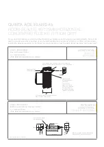
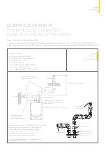
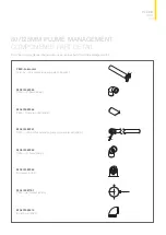
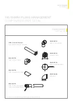
Standard length 
‘L’ = 1000mm Part No. MG87062 
‘L’ = 500mm Part No. MG87061 
‘L’ = 250mm Part No. MG87060

Condensate drain 
Part No. MG410085130

Reducer 80mm spigot to 100mm 
Part No. MG87127 
Must be used on the QACE 30/45 flue socket 
connection to adapt to 100mm system

Air Inlet guard 
Part No. PU002

90° Bend 
Part No. MG87113

45° Bend 
Part No. MG87103

Note: 
2 x 45° bends will  
offset to 71mm centres

Flue terminal c/w bird guard 
Part No. PU001

Twin pipe adaptor plate 
Part No. S100250

Mounting bracket 
Part No. MG87193

8mm x 45mm 
screw thread

Silicon seal ring 
Part No. MG87183

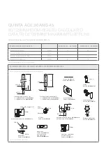
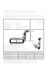
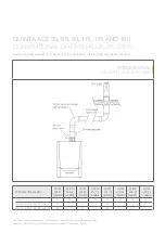
OPEN-FLUE DATA

QUINTA ACE 30 100MM

QUINTA ACE 45 100MM

Maximum overall flue run

Metres

40

40

Reduction length for each 45° bend

Metres

1.4

1.4

Reduction length for each 90° bend

Metres

4.9

4.9

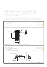
Cut down to suit diameter of flue in use 
and seal with silicone supplied

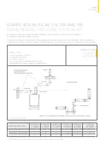
Detail of standard weathering plate for 

100mm to 150mm flue (Part No. VE001)

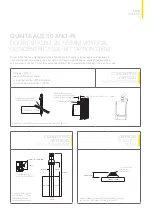
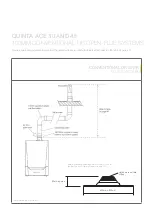
Standard length  
‘L’= 1000mm Part No. MG87062 
‘L’= 500mm Part No. MG87061 
‘L’= 250mm Part No. MG87060

Reducer 80 spigot to 100 socket 
Part No. MG87127 
Must be used on the QP 30/45 flue 
connection to adapt to 100mm system

Flue terminal c/w bird guard 
Part No. PU001

90° bend 
Part No. MG87113

Note:  
2 x 45° bends will offset 
to 71mm centres

45° bend 
Part No. MG87103

Air inlet guard 


Part No. PU002

Condensate drain  
Part No. MG410085130

Mounting bracket  
Part No. MG87193

Silicon seal ring  
Part No. MG87183

Eccentric flue connector


80/80 – Part No. S100250

100/100 – Part No. S101626

Siphon 

Part No. MG410081165

268 ± 3

Siphon adaptor kit
Part No. MG410087491

101 i/d

50

100 o/d

'L

'

125

101 i/d

80 o/d

600mm x 500mm

80 approx

20

30

95

10

101 i/d

101 i/d

Top

10

200

60

76

76

105

105

180mm

100mm

25mm ID/32mmO/D

25-55mm

8mm x 45mm

screw thread

Содержание Quinta Ace 115

Страница 1: ...QUINTA ACE RANGE ...

Страница 2: ...D CONTROLS 27 QUINTA ACE 135 AND 160 SPECIFICATIONS 30 FLUE OPTIONS 52 FLUECADE SYSTEM 53 FLUECADE KITS 57 FLUECADE COMPONENTS 61 CASCADE OPTIONS 63 INSTALLATION AND CONFIGURATION 68 BESPOKE RIG SYSTEMS 71 TECHNICAL SUPPORT 71 DECLARATION OF COMPLIANCE In the interests of the quality of our products we strive constantly to improve them We therefore reserve the right to modify the specifications an...

Страница 3: ...odels With their extremely compact design the Quinta Ace range can be installed individually or as part of a multi boiler cascade or rig system for flexible design and reliable high quality performance The Quinta Ace range is suitable for use on sealed systems and open vented except the Quinta Ace 135 and 160 installations High efficiency boiler up to 97 6 GCV Higher than average energy savings Sm...

Страница 4: ...essure sensor 3 Flue gas measuring point 10 Return sensor 17 Fan 4 Interior light 11 Air intake silencer 18 Supply line 5 Flow sensor 12 Instrument box 19 Flue gas discharge pipe 6 Ionisation ignition electrode 13 Siphon 20 Air supply 7 Mixing tube 14 Box for the control PCBs accessory QUINTA ACE 30 115 BOILER CONSTRUCTION ...

Страница 5: ...CONSTRUCTION Contact us for 4 4 2 2 1 12 2 C Ca as sc ca ad de e The boiler is ideally s standard solutions av I Im mp po or rt ta an nt t Contact us for 4 4 3 3 M Ma ai in n c co om mp po on ne en nt ts s 1 1 Air supply flue 2 2 Casing air box 3 3 Interior light 4 4 Flow sensor 5 5 Adapter 6 6 Heat exchang 7 7 Temperature s 8 8 Ignition transfo 9 9 Inspection hat 1 10 0 Water pressur 1 11 1 Retur...

Страница 6: ...iler from flue lengths greater than one metre must be discharged via a condensate collector and drain system fitted within one metre of the boiler flue connection Combustion air is drawn into the closed air box by a variable speed fan through the air inlet connection from the plant room open flued or from outside via the concentric flue system room sealed On the inlet side of the fan is a speciall...

Страница 7: ...on kWh 91 125 173 188 N a N a N a N a GAS Standard fuel Natural gas Natural gas Natural gas Natural gas Natural gas Natural gas Natural gas Natural gas Optional fuel adjustment see installation and service manual LPG propane LPG propane LPG propane LPG propane LPG propane LPG propane LPG propane LPG propane Gas consumption NG m3 h 0 9 3 2 0 9 4 4 1 2 6 0 1 3 6 6 1 5 9 1 2 1 11 3 3 4 13 9 3 4 16 5 ...

Страница 8: ...l weight including packaging kg 60 5 60 5 66 5 66 5 76 5 76 5 147 147 Min mounting weight without front panel kg 50 50 56 56 65 65 123 123 Dimension mm WxHxD 500x750x500 500x750x500 500x750x500 500x750x500 500x750x500 500x750x500 600x1045x602 600x1045x602 NOx Dry 0 O2 NCV EN15502 Class 6 Mg kWh 33 33 36 36 29 33 24 36 Noise levels dB A at 1 metre 38 3 45 1 46 7 46 7 51 6 51 1 59 5 59 5 Eco design ...

Страница 9: ...n Should a negative effect happen in the system the boiler will reduce its output and or shut down shut off mode awaiting the negative conditions to return to normal before re starting The control cannot override the standard flame safety controls Standard frost protection will activate below 7 C with stage one activating system shunt pump Stage two will activate below 3 C with boiler switching on...

Страница 10: ...lockout condition Should a negative effect happen in the system the boiler will reduce its output and or shut down shut off mode awaiting the negative conditions to return to normal before re starting The control cannot override the standard flame safety controls Standard frost protection will activate below 7 C with stage one activating system shunt pump Stage two will activate below 3 C with boi...

Страница 11: ...stion gas exhaust pipe Ø 80mm 45kW Ø 100mm 55kW Connection of the air intake pipe Ø 125mm 45kW Ø 150mm 55kW Siphon connection bush Heating circuit return 1 Male thread 32mm Gas connection Male thread 22mm Heating circuit flow 1 Male thread 32mm QUINTA ACE DIMENSIONS AND CONNECTIONS 11 ENGINEERING SPECIFICATION DIMENSIONS AND CONNECTIONS ...

Страница 12: ...supply connection Ø 150mm Siphon connection 32mm Flow connection 1 Male thread 32mm Return connection 1 Male thread 32mm Gas connection 1 Male thread 28mm QUINTA ACE 135 AND 160 DIMENSIONS AND CONNECTIONS 425 300 240 110 1045 600 143 602 226 80 ...

Страница 13: ...lly Earths are omitted for clarity 13 TYPICAL INSTALLATIONS The schematics presented within this document are generic and therefore are not representative of a design for a specific site application It is the responsibility of the specifier and the installer to ensure that all system components are appropriately sized for the specific ...

Страница 14: ... Ace 30 45 55 65 90 and 115 boilers heating and domestic hot water using a simple S plan QUINTA ACE TYPICAL INSTALLATION Note Control PCBs are shown diagrammatically Some earths and neutrals are omitted for clarity ...

Страница 15: ...ump PM1 Flow Return Time temp control volt free Pump PM1 Factory fitted fly lead Shunt pump SH1 Alternative 0 10v control BR BL GN YW BR BL GN YW 1 3 2 X1 Main control PCB PCB SCU S02 PCB SCU X01 PCB IF 01 PUMP X81 Status Status Status Egv Pump hws 3wv OT BL RL Tout Tdhw 15 TYPICAL INSTALLATION Note Control PCBs are shown diagrammatically Earths are omitted for clarity ...

Страница 16: ...Note When using the Remeha supplied low loss header and pump kit and the DHW diverting valve or primary pump kit the calorifier must be sited within 3m of the boiler In both cases the DHW cylinder must be a high recovery unit capable of accepting the full or adjusted DHW output of the boiler used Control PCBs are shown diagrammatically Earths are omitted for clarity ...

Страница 17: ...LATION 17 TYPICAL INSTALLATION Note When using the Remeha supplied low loss header and pump kit and the DHW diverting valve or primary pump kit the calorifier must be sited within 3m of the boiler In both cases the DHW cylinder must be a high recovery unit capable of accepting the full or adjusted DHW output of the boiler used Control PCBs are shown diagrammatically Earths are omitted for clarity ...

Страница 18: ...ndensate 230v supply 100m Max Pump PM1 1 6M Suggested height in room Normal position for the iSense controller mounted in reference room within the building room compensation Pump PM1 on off or modulating controls OT PCB SCU S02 PCB SCU X01 PCB IF 01 Factory fitted supply lead to be connected to a 230v fused spur for boiler permanent supply PUMP X81 Egv hws 3wv Pump Note Control PCBs are shown dia...

Страница 19: ...ly lead to PUMP X81 Egv hws 3wv Pump 1 6M Suggested height in room Normal position for the controller mounted in reference room within the building iSense can be fitted in the boiler if used for weather compensation only 100m Max Condensate Gas Flow Return 100m Max Outside sensor on North facing wall Pump PM1 230v supply X1 Pump PM1 Outside sensor on off or modulating controls OT Note Control PCBs...

Страница 20: ...E TYPICAL INSTALLATION Note When using the Remeha supplied low loss header and pump kit and the DHW diverting valve or primary pump kit the calorifier must be sited within 3m of the boiler In both cases the DHW cylinder must be a high recovery unit capable of accepting the full or adjusted DHW output of the boiler used Control PCBs are shown diagrammatically Earths are omitted for clarity ...

Страница 21: ...CE TYPICAL INSTALLATION 21 TYPICAL INSTALLATION Note When using the Remeha supplied low loss header and pump kit and the DHW diverting valve or primary pump kit the calorifier must be sited within 3m of the boiler In both cases the DHW cylinder must be a high recovery unit capable of accepting the full or adjusted DHW output of the boiler used Control PCBs are shown diagrammatically Earths are omi...

Страница 22: ...ted supply lead to be connected to a 230v fused spur for boiler permanent supply PUMP X81 Egv hws 3wv Pump X1 iSense can be mounted in boiler for weather compensation only 100m max Outside sensor on North facing wall 230v supply 230v supply Celcia MC4 Pump PM1 Htg flow sensor Condensate Gas Flow Return T w o t o f o u r b o i l e r s iSense mounted in reference room or boiler for weather compensat...

Страница 23: ...Suggested hydraulic circuit diagram QUINTA ACE 135 AND 160 TYPICAL INSTALLATION Note This information is indicative 23 TYPICAL INSTALLATION Hot water cylinder ...

Страница 24: ...s corrected the boiler can be restarted by using the reset key on the control panel LOW WATER PROTECTION FLOW AND CONTENT The Quinta Ace range is supplied with a low water protection on the basis of a low water pressure switch and also by temperature measurement By modulating down at the moment that the water flow threatens to fall too low the boiler is kept operating for as long as possible EXTER...

Страница 25: ...meha MC4 in conjunction with the iSense controller can provide step control for multi boiler installation of up to four boilers ON OFF VOLT FREE CONTROL FROM A THIRD PARTY INSTALLER Connect a two wire cable to terminal R Bus which must be a volt free connection from the third party controller Analogue control 0 10V d c The heat output modulates between the minimum and the maximum values on the bas...

Страница 26: ... be discussed with specialist water treatment companies in respect to aluminium heat exchangers For further information Remeha Water Quality Regulations is available from remeha co uk The recommendations in the document must be followed FROST PROTECTION Install the boiler in a frost free room The built in frost protection system is activated as follows below 7 C system pump is switched on if conne...

Страница 27: ... 1 4 X09 1 4 X08 1 13 X083 X07 1 4 X071 X06 1 4 X04 X05 1 15 X041 X051 X053 X054 X055 X081 X02 1 9 X03 1 15 X021 X022 X032 X031 X016 X015 X01 1 7 X0141 X014 230V 50Hz X011 X013 X012 X20 X202 X201 EMC 20 19 18 17 16 15 14 13 12 11 10 9 8 7 6 5 3 4 2 1 21 21 KEY 1 Boiler control unit 8 Control fascia panel 15 Air pressure differential switch 2 Lighting 9 Fan supply 16 Flue gas sensor 3 Ignition prob...

Страница 28: ...et key on the control panel LOW WATER PROTECTION FLOW AND CONTENT The Quinta Ace range is supplied with a low water protection on the basis of a low water pressure switch and also by temperature measurement By modulating down at the moment that the water flow threatens to fall too low the boiler is kept operating for as long as possible EXTERNAL CONNECTIONS All external connections are made to any...

Страница 29: ...the interface is used to select either temperature control or heat output control ANALOGUE OUTPUT CAPACITY CONTROL The 0 10V signal controls the boiler output between 0 and 100 of its total capacity kW The minimum and maximum values are limited The minimum output is linked to the boiler s modulation depth The output varies between the minimum and maximum value on the basis of the value determined ...

Страница 30: ...y gases Ref BS 6644 Specification for installation of gas red hot water boilers of rated inputs between 70kW to 1 8MW net 2nd and 3rd family gases Ref IGE UP 10 Installation of flued gas appliances in industrial and commercial premises It is the responsibility of the installer to install the flues and fluecades to comply with the current regulations and standards IMPORTANT NOTE All flue terminals ...

Страница 31: ...e inner concentric connection with the air supply taken from the boiler house via the outer concentric connection In order to prevent the spilling of combustion products a condensate trap not supplied must be fitted on the plastic drain connection on the condensate drain which is available as an option with horizontal and vertical flue terminals DETAILS OF CONDENSATE DRAIN Flue gas Air in TO SUITA...

Страница 32: ...m holes 204 Sq 110mm 50mm insertion length into mating socket 80mm o d 95mm 145mm Clearance hole for terminal through wall 130mm Note 140mm diameter recessed 15mm deep required from the surface of the inside wall to allow clearance for the bend Cut terminal on site to suit wall thickness Max 1000mm Min 150mm Wall closures plate should be fitted to terminal before passing through hole in wall to en...

Страница 33: ...Condensate drain Part No MG410084472 87 90 180mm RAL 7021 300mm 1350mm 755mm RAL 9016 Dn80 Dn125 80mm approx 600mm x 500mm QP30 45 495mm 25mm I D 32mm O D Weathering slate suitable for flat or pitched roof 60 87 90 180mm RAL 7021 300mm 1350mm 755mm RAL 9016 Dn80 Dn125 80mm approx 30 45 495mm 25mm I D 32mm O D 87 90 180mm RAL 7021 300mm 1350mm 755mm RAL 9016 Dn80 Dn125 80mm approx 600mm x 500mm QP3...

Страница 34: ...G410081302 Standard length cannot be cut L 1000mm Part No MG410084486 L 500mm Part No MG410084485 Standard length cuttable length L 1000mm Part No MG410082314 L 500mm Part No MG410082313 125 i d 80mm o d 25mm I D 32mm O D 180mm 87 90 80 o d 125 i d 110 95 145 90 Boiler short bend Part No MG410084810 90 Bend Part No MG410084460 45 Bend Part No MG410084461 Condensate drain Part No MG410084472 158mm ...

Страница 35: ... to replace standard concentric fitting 100 80mm reducers to adapt boiler to suit 100mm system if required Flue terminal c w bird guard Condensate drain Air inlet guard 100 80mm reducer x2 Two pipe adaptor plate Part No S100250 100mm aluminium single wall flue and air inlet system Flue outlet Air inlet Fall from boiler Fall to boiler Condensate drain Quinta Ace 30 45 two pipe adaptor plate is requ...

Страница 36: ...in the table on page 40 100mm aluminium single wall flue system Flue outlet Fall to boiler Condensate drain Air from plant room Refer to table on page 35 100 80mm reducer to adapt boiler to suit 100mm system 80mm approx Cut down to suit dia of flue 600mm x 500mm Detail of standard weathering plate for 100mm to 150mm flue Part No ve001 flat or pitched roofs up to 60 Note Fall to boiler 50mm Mtr ...

Страница 37: ...ket connection to adapt to 100mm system Air Inlet guard Part No PU002 90 Bend Part No MG87113 45 Bend Part No MG87103 Note 2 x 45 bends will offset to 71mm centres Flue terminal c w bird guard Part No PU001 Twin pipe adaptor plate Part No S100250 Mounting bracket Part No MG87193 8mm x 45mm screw thread Silicon seal ring Part No MG87183 OPEN FLUE DATA QUINTA ACE 30 100MM QUINTA ACE 45 100MM Maximum...

Страница 38: ...gulations and British Standards with regards to the minimum distances from openings walls etc Flue can be taken directly through rear outside wall or discharged through a side wall left or right Both must be within the constraints in the table below 80 125mm Plume Management details Calculations based on products supplied by Remeha Note 2 Fall to boiler 50mm Mtr 7 Flue outlet 80mm 8 Bird guard 1 x...

Страница 39: ...lume Management Kit PMK horizontal Terminal not supplied as a separate component MG410082343 PMK 90 bend 80mm MG410082344 PMK horizontal outlet 80mm MG410082341 PMK 1000mm flue extension piece c w wall bracket 80mm MG410082342 PMK 45 bend 80mm MG410082345 Bird mesh 80mm MG410087191 PMK wall bracket 80mm MG410084810 Boiler bend 80mm ...

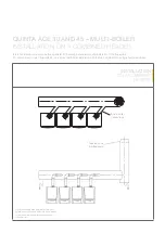
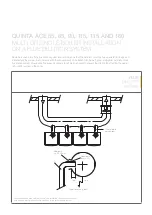
Страница 40: ...stem For conventional or open flue systems on a typical multi boiler installation with the flue combined into a single header and riser INSTALLATION ON A COMBINED HEADER 80mm boiler connections Tapered cone c w bird guard For illustration purposes only we recommend installation of condensate collectors with drainage system and water sealed siphon to the spigot of each boiler ...

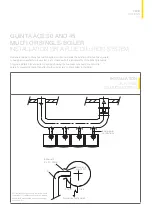
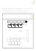
Страница 41: ...l installation for a flue dilution system showing the flue break necessary for all pre mix boilers to prevent the dilution fan affecting the gas air ratio control system in the boiler INSTALLATION ON A FLUE DILUTION SYSTEM 80mm boiler connections Bellmouth 2 x D 50mm Opening in duct 2 x D Drain 30mm D Typical duct entry detail 41 FLUE OPTIONS For illustration purposes only we recommend installation ...

Страница 42: ...l terminal Note boiler bend and wall plate are included EXTENDED HORIZONTAL FLUE KIT 100 150MM Please note All dimensions are in mm 45mm insertion length into mating socket BS RAL colour 9016 7021 HRS room sealed terminal 100 150 MG410082981 MG410081941 150 o d 150 min 500 1000 max 100 o d 790 1135 115 140 240 Sq 4 x 5mm holes 204 Sq Detail of the 100 150mm horizontal concentric flue kit option QP...

Страница 43: ...01 Kit parts KT00310 Contains optional condensate drain VERTICAL FLUE KIT 100 150MM Additional components required to suit site details within boiler constraints Weathering slate suitable for flat or pitched roof QACE 55 65 90 115 100mm QACE 135 160 226mm Condensate drain QACE 55 65 90 115 135 160 615mm Detail of the vertical 100 150mm Concentric Flue Kit KT1216 Can be cut on site to a minimum of ...

Страница 44: ...s 210 151 i d 115 115 150 i d 100 o d 150 115 150 i d 150 180mm 87 90 150 o d 25mm i d 32mm o d Standard length 1000mm Part No MG410084336 500mm Part No MG410084335 Cuttable length 1000mm Part No MG410082318 500mm Part No MG410082317 Internal wall plate Part No MG410081303 Silicon seal ring flue side Part No MG410027356 90 bend Part No MG410084310 45 bend Part No MG410084313 90 boiler short bend Pa...

Страница 45: ... the combustion gas discharge is 36m Kit parts KT030 1 x flue connection S101626 1 x flue terminal PU001 1 x air inlet PU002 1 x condensate drain MG410085130 x siphon MG410081165 x condense adaptor kit MG41008749 TWO ZONE FLUE KIT 100 150MM Note 2 Maximum permitted height difference between combustion air supply and flue gas outlet is 36m ROOM SEALED FLUE DATA QUINTA ACE 55 100MM Ø QUINTA ACE 65 1...

Страница 46: ...efer to Remeha technical department for further details Not supplied by Remeha CONVENTIONAL OR OPEN FLUE SYSTEMS OPEN FLUE DATA 100MM QUINTA ACE 55 100MM Ø QUINTA ACE 65 100MM Ø QUINTA ACE 90 100MM Ø QUINTA ACE 115 100MM Ø QUINTA ACE 135 100MM Ø QUINTA ACE 135 150MM Ø QUINTA ACE 160 100MM Ø QUINTA ACE 160 150MM Ø Maximum overall flue run M 39 26 24 19 12 40 8 40 Reduction length for each 45 bend M...

Страница 47: ...G87113 Note 2 x 45 bends will offset to 71mm centres 45 bend Part No MG87103 Air inlet guard Part No PU002 Condensate drain Part No MG410085130 Mounting bracket Part No MG87193 Silicon seal ring Part No MG87183 Eccentric flue connector 80 80 Part No S100250 100 100 Part No S101626 Siphon Part No MG410081165 268 3 Siphon adaptor kit Part No MG410087491 101 i d 50 100 o d L 125 101 i d 80 o d 600mm ...

Страница 48: ...rizontal terminal kit installed 5 5 4 7 8 6 1 3 3 Note 2 Both the concentric flue terminal and plume flue outlet positions of the PMK must comply with the current regulations and British Standards with regards to the minimum distances from openings walls etc Flue can be taken directly through rear outside wall or discharged through a side wall left or right Both must be within the constraints listed...

Страница 49: ... MG410081753 PMK 90 bend 100mm MG410081754 PMK horizontal outlet 100mm MG410081751 PMK 1000mm glue extension piece c w wall bracket 100mm Dn 100 Dn 100 Dn 100 MG410081752 PMK 45 bend 100mm MG410081755 Bird mesh 100mm MG410087193 PMK wall bracket 100mm MG410084360 Boiler bend Note The components listed above must only be used as part of the Plume Management Kit ...

Страница 50: ...e dilution system showing the flue break necessary for all pre mix boilers to prevent the dilution fan affecting the gas air ratio control system in the boiler FLUE DILUTION SYSTEM Typical duct entry detail 100mm boiler connections Bellmouth 2 x D 50mm D Opening in duct 2 x D 30mm Drain Typical duct entry detail 100mm boiler connections Bellmouth 2 x D 50mm D Opening in duct 2 x D 30mm Drain For i...

Страница 51: ...entional or open flue systems in a typical multi boiler installation with the flue combined into a single header and riser 100mm boiler connections Tapered cone c w bird guard For illustration purposes only we recommend installation of condensate collectors with drainage system and water sealed siphon to the spigot of each boiler Note Using 90 boiler connections into the header may result in large...

Страница 52: ...e The system comes complete with all associated components Optional adaptors are available which can be connected to the last boiler connection Refer to table on page 58 The flue can then continue to the external exit point and termination using suitable flue products components The flue header is supplied in 200mm only and is CE approved Only the components and accessories listed on pages 55 to 5...

Страница 53: ...rt No MG410085141 x 2 6 Cover PP 200 and Condensate Part No MG410071526 x 1 THIS BASIC PP 200MM FLUECADE HEADER KIT IS SUITABLE FOR THE CONNECTION OF TWO QUINTA ACE BOILERS IN AN IN LINE CONFIGURATION Please refer to table on page 58 to determine the maximum length and diameter of the fluecade system for the Quinta Ace range of boilers Note The Quinta Ace 30 and Quinta Ace 45 boilers also require ...

Страница 54: ...76748 x 1 IN LINE CONFIGURATION THIS BASIC PP 200MM FLUECADE EXTENSION KIT IS SUITABLE FOR THE CONNECTION OF AN EXTRA QUINTA ACE BOILER IN AN IN LINE CONFIGURATION Please refer to table on page 58 to determine the maximum length and diameter of the fluecade system for the Quinta Ace range of boilers Note The Quinta Ace 30 and Quinta Ace 45 boilers also requires the 80 125 boiler connection kit MG4...

Страница 55: ...o MG410071526 x 1 2 Air inlet grill 100 150 Part No MG410075435 x 2 6 Expander PP 100 150 Part No MG410085635 x 2 10 Extension PP 200 L 500 Part No MG410070401 x 1 3 Elbow short PP 100 45 Part No MG410085142 x 2 7 Collector PP 200 2 x 100 45 L 585 Part No MG410081949 x 1 11 Wall bracket 200 Part No MG410087198 x 3 4 Elbow short PP 100 90 Part No MG410085141 x 2 8 Syphon PP h 150 Part No MG41008116...

Страница 56: ...1 x 2 4 Elbow short PP 100 90 Part No MG410085141 x 2 7 Collector PP 200 2 x 100 45 L 585 Part No MG410081949 x 1 2 Air inlet grill 100 150 Part No MG410075435 x 2 5 Reducer PP 150 100 Part No MG410071518 x 2 8 Wall bracket 200 Part No MG410087196 x1 3 Elbow short PP 100 45 Part No MG410085142 x 2 6 Expander PP 100 150 Part No MG410085635 x 2 BACK TO BACK CONFIGURATION Note Quinta Ace 30 and Quint...

Страница 57: ...art No MG410070412 Straight flue 200mm x 770mm Part No MG410070420 Air intake grill parallel 80mm Part No MG410076039 Air intake grill parallel 100mm Part No MG410079314 Air intake grill concentric 80 125mm Part No MG410075434 Air intake grill concentric 100 150mm Part No MG410075435 Flue header 200mm Part No MG410081949 57 FLUECADE KITS FLUECADE COMPONENTS Note All PP Fluecade components are desi...

Страница 58: ...90 Seal HR EPDM 200mm Part No MG410027360 Seal HR EPDM 150mm Part No MG410027358 Seal HR EPDM 100mm Part No MG410027356 Condense adaptor Kit parts MG410087491 100mm 45 elbow Part No MG410085142 90 elbow 100mm Part No MG410085141 Straight flue 100mm x 500mm Part No MG410085481 Note All PP Fluecade components are designed for internal use only ...

Страница 59: ... 300mm 175cm2 Part No MG410087433 200mm flat roof flashing Part No MG410079612 200mm chimney cap Part No MG410087398 Straight flue 200mm x 1000mm Part No MG410070402 Cover plate 300mm x 300mm with sleeve 250mm x 300mm Part No MG410081362 59 FLUECADE COMPONENTS Note All PP Fluecade components are designed for internal use only ...

Страница 60: ...17M 59 6 81 6 2 x QACE 30 45 150 150 150 150 89 4 122 4 3 x QACE 30 45 150 150 150 150 119 2 163 2 4 x QACE 30 45 150 150 150 150 149 204 5 x QACE 30 45 150 150 150 150 178 8 244 8 6 x QACE 30 45 150 150 150 150 110 6 2 x QACE 55 150 150 150 150 165 9 3 x QACE 55 150 150 150 150 221 2 4 x QACE 55 150 150 150 150 276 5 5 x QACE 55 150 150 150 150 331 8 6 x QACE 55 150 200 150 200 150 200 150 200 12...

Страница 61: ... been made in the frame into which this pipe can be fitted to the left or right as required sloping downwards Quinta Ace 30 45 55 65 90 and 115 boilers are particularly suitable for use in cascade systems due to their small footprint and width of only 50cm which allows an exceptionally compact cascade configuration For example when using six Quinta Ace 115 boilers in line including low loss header...

Страница 62: ...he cascade systems can be divided into three main groups two to eight boilers in a linear configuration wall mounted two to eight boilers in a linear configuration mounted on a free standing frame three to ten boilers in a back to back configuration mounted on a free standing frame The boiler side of the cascade systems is sized to 20ºC The low loss header is based on 20 11ºC DIMENSIONS MM BOILERS ON...

Страница 63: ... return connection 200mm Y Distance to system flow connection 560mm 63 INSTALLATION DRAWINGS AND LINEAR CONFIGURATION QUINTA ACE LINEAR CONFIGURATION MOUNTED ON A FREE STANDING FRAME TWO TO EIGHT BOILERS T003419 A 500 284 500 A B 0 9 5 1 0 9 5 1 OV 3150 3230 30 500 Y X 100 1306 270 1576 555 530 231 DIMENSIONS MM BOILERS FRAME ONLY NO OF BOILERS 2 3 4 5 6 7 8 Width mm 1110 1640 2170 2700 3230 3760 ...

Страница 64: ...ction 200mm Gas supply connection DN 50 or 65 DIN 2633 4 holes Air inlet flue gas discharge concentric connection Quinta Ace 30 45 80 125mm Quinta Ace 55 65 90 115 100 150mm B System return connection DN 100 or 125 DIN 2631 8 holes Y Distance to system flow connection 560mm OV Low loss header DN 65 633mm DN 100 643mm 500 30 2620 2650 0 0 5 200 530 500 1055 100 1306 1576 325 125 A B OV Y X Note This...

Страница 65: ...frame KEY A System Flow Connection DN 125 DIN 2633 8 holes X Distance to system return connection 200mm Gas supply connection DN65 DIN 2633 4 holes Air inlet flue gas discharge concentric connection 100 150mm B System Return Connection DN 125 DIN 2633 8 holes Y Distance to system flow connection 560mm OV Low loss header DN 100 633mm QUINTA ACE 135 AND 160 STRUCTURE OF QUINTA ACE 135 AND 160 CASCADE...

Страница 66: ...ers in a back to back configuration mounted on a free standing frame KEY A System Flow Connection DN 125 DIN 2633 8 holes X Distance to system return connection 200mm Gas supply connection DN65 DIN 2633 4 holes Air inlet flue gas discharge concentric connection 100 150mm B System Return Connection DN 125 DIN 2633 8 holes Y Distance to system flow connection 560mm OV Low loss header DN 100 633mm QUI...

Страница 67: ...ilers Please contact your local Sales Manager for further information Contact details are available via the website remeha co uk Quinta Quinta ACE 160 Quinta 30 mm 80 mm 1924mm 5 mm 1603 5mm 5 mm 500 mm 600 mm 600 mm ACE 30 45 55 65 90 115 ACE 160 67 INSTALLATION AND CONFIGURATION QUINTA BOILER CASCADES Note Please take into account boiler and component weights ...

Страница 68: ... our website remeha co uk BESPOKE RIG SYSTEMS DN50 NP16 DIN 2633 gas supply 427 5 175 XC065FK45 50 x 50mm frame 1785 500 1640 700 View without insulation 5 375 466 110 40 condensate discharge 375 550 305 DN100 NP6 DIN 2631 system flow return 530 152 2462 668 1304 DN50 NP16 DIN 2633 gas supply 427 5 175 XC065FK45 50 x 50mm frame 1785 500 1640 700 View without insulation 5 lit dosing pot 375 466 110...

Страница 69: ...ondensate View without insulation 428 215 320 2184 Exp vessel 630 630 705 3782 1900 1086 3x Quinta Ace 160 Dosing pot PHE 480 kW 2880 1065 DN100 PN16 EN1092 1 system flow return 1024 40 condensate View without insulation DN65PN16 DIN2633 gas connection 428 215 320 2210 2184 2163 Exp vessel 630 630 705 3782 1900 1086 3x Quinta Ace 160 Dosing pot PHE 480 kW 2880 1065 DN100 PN16 EN1092 1 system flow ...

Страница 70: ......
Страница 71: ...eets Case studies Installation manuals BIM files CAD files Energy related products directive data Commissioning Technical information Spare parts after sales DECLARATION OF COMPLIANCE The boiler meets the requirements of the EC regulations and directives Gas Appliances Regulations EU 2016 426 Boiler Efficiency Directive 92 42 EEC Low Voltage Directive 2014 35 EU EMC Directive 2014 30 EU ErP 2009 1...

Страница 72: ...ng UK Ltd Brooks House Coventry Road Warwick CV34 4LL Quinta Ace Specification Guide February 2021 Innovation House 3 Oaklands Business Centre Oaklands Park Wokingham RG41 2FD T 0345 070 1055 E info baxiheating co uk W remeha co uk ...

Отзывы: