27
QUINTA ACE
CONTROLS AND SPECIFICATIONS
QUINTA
ACE 135 AND 160
SPECIFICATIONS
The boiler has a three-wire mains lead (lead length 1.5m) and is
suitable for a 230VAC/50Hz power supply with a phase/neutral/
earth system. The boiler is not phase sensitive and the boiler is
completely pre-wired.
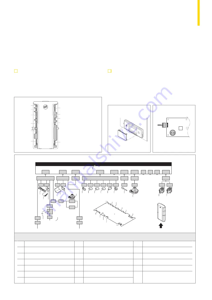
ASSEMBLY OF THE CONTROL PANEL
The Human Machine Interface (HMI) and the connection box need
to be fitted. The connection box contains standard control PCB
CB-01 and expansion board SCB-01 for external connections.
The optional PCBs are also placed in the connection box.
For further information, please refer to the Installation and
Service Manual for the boiler and the control panel.
X07
X08
X10
X09
X11
X12
X06
X05
X04
X03
X02
X01
Connectors from
the control unit
CU GH06 (Front view)
Control panel
HMI PCB
AD-0000669-05
X01
X02
X03
X04 / X05
X06
X07
X12
X11
X10
X09
X08
Pump
N
L
OT
On/off
0
+
0 - 10
0
+
PWM
BL
RL
Tout
X1
X8
X10
X4
X9
X5
X6
X2
X3
X1
1
3
2
X2
1
3
2
Pump
N
L
X3
1
3
2
4 5 6 7 8 9 10 11 12
On/off
OT
PWM
0
+
0 - 10
0
+
Tout
BL
RL
X4
1
7
-
6.3 AT
F1
X019
X039
X036
X5
1
7
-
X6
1
15
-
CB-01
X018
X017
X035
X033
X020
230VAC
X038
Bus
X037
Bus
CU-GH & HMI
X12
1
5
-
X122
X121
X11
1- 4
X10
1- 4
X09
1- 4
X08
1
13
-
X083
X07
1
4
-
X071
X06
1
4
-
X04 / X05
1
15
-
X041
X051
X053
X054
X055
X081
X02
1
9
-
X03
1
15
-
X021
X022
X032
X031
X016
X015
X01
1
7
-
X0141
X014
230V, 50Hz
X011
X013
X012
X20
X202
X201
EMC
20
19
18
17
16
15
14
13
12
11
10
9
8
7
6
5
3
4
2
1
21
21
KEY
1
Boiler control unit
8
Control fascia panel
15
Air pressure differential switch
2
Lighting
9
Fan supply
16
Flue gas sensor
3
Ignition probe
10
Programmable storage unit
17
Fan control (PWM)
4
Ignition transformer
11
Flow sensor
18
Gas valve 1
5
Power supply
12
Heat exchanger sensor
19
Gas valve 2
6
N/a
13
Return sensor
7
Service connector/computer connection
14
Hydraulic pressure sensor
66..66..33
AAsssseem
mbbllyy ooff tthhee ccoonnttrrooll ppaanneell
The Quinta Ace boiler is supplied with a separate control panel. The
control panel is mounted in the boiler. The cable in the box with connector
XX002211 must be slid onto the connector pin (5 pins, 24 V) of the PCB.
BB Battery
There is also a back-up battery on the PCB for the internal clock. Check
the battery voltage if the date and time are not displayed clearly.
Fig.24
Control panel
AD-0000628-02
Fig.25
PCB
AD-0001300-01
B
X021
6 Installation
36
7701860 - v.04 - 06012021
Содержание Quinta Ace 115
Страница 1: ...QUINTA ACE RANGE ...
Страница 70: ......


