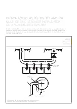
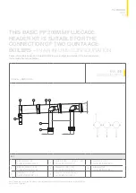
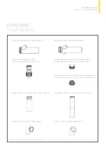
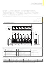
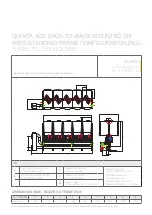
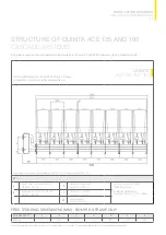


Free-standing frame configuration.
KEY
A
System flow; connection DN 100
or 125/DIN 2631 (8 holes)
OV
Low loss header
DN 65 = 633mm
DN 100 = 643mm
Gas supply connection
DN 50 or 65/DIN 2633 (4 holes)
Air inlet/flue gas discharge
concentric connection
Quinta Ace 30/45 = 80/125mm
Quinta Ace 55/65/90/115 = 100/150mm
B
System return; connection DN 100
or 125/DIN 2631 (8 holes)
X
Distance to system return
connection = 200mm
Y
Distance to system flow connection = 560mm
63
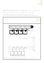
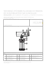
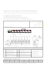
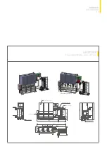
INSTALLATION DRAWINGS
AND LINEAR CONFIGURATION
QUINTA ACE LINEAR CONFIGURATION,
MOUNTED ON A FREE-STANDING FRAME
–
TWO TO EIGHT BOILERS
T003419-A
500
284
500
A
B
0
9
5
1
0
9
5
1
OV
3150
3230
30
500
Y
X
100
1306
270
1576
555
530
231
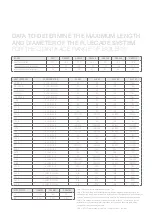
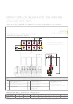
DIMENSIONS (MM) - BOILERS & FRAME ONLY
NO. OF BOILERS
2
3
4
5
6
7
8
Width mm
1110
1640
2170
2700
3230
3760
4290
Note This information is provided as a guide only. Please refer to the Quinta Pro Cascade Installation and Service Manual for specific details.
QUINTA
ACE 30, 45, 55,
65, 90 AND 115
Содержание Quinta Ace 115
Страница 1: ...QUINTA ACE RANGE ...
Страница 70: ......