8
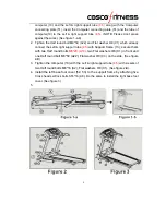
computer (10) and the Left & right support tube
(4.5)
along with the Computer
connecting plate (51), insert the Computer connecting plate (51) and the tube of
computer(10) to the Left & right support tube
(4.5).
(NOTE: Please don’t press
against the wires.) (See figure 1-a-b)
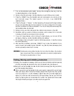
2. Tighten the Half round bolt M8*50 (A22) and Flat washer
Ф
8 (C1) which already
connect the Left & right support tube
(4.5)
with
Support frame (13); secure them
with two Half round bolts
M8*20 (A19),
two Flat washers
Ф
8 (C1) in front and
one Half round bolt M8*50 (A22), Flat washer
Ф
8 (C3) on the side.
(See figure
2-B)
3.
Tighten the computer (10) with the
Left & right support tube
(4.5)
with six sets of
two Half round bolts M8*16 (A2), Flat washers
Ф
8 (C1).
(See figure 2-B)
.
4.
Install the left base foot cover (52, 53) to the support frame by attaching five
Cross head self-lock bolts ST4*16 (A8). Do the same to install the right base foot
cover. (See figure 3)
5.


