Hardware Manual — Installation and Configuration Options
2.2.1 Packing List
The Packing list (refer to Appendix A) contains a list of all of the items included
in the shipping box. It is a detailed list identifying the modules and components
of the Centurion II and their serial numbers. The module serial numbers are
located on the inside of the module faceplates and on the bottoms of the module
circuit boards.
Proper ESD precautions should be used at all times when verifying the serial
numbers. The technician should use the Packing list to verify both the contents of
the box and the serial numbers of all of the components within the Centurion II.
Any errors or omissions should be reported to Cordell, Inc.
2.2.2 Installing the RTU
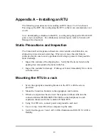
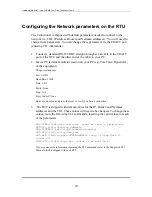
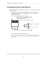
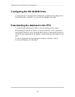
Appendix B —
Installing the RTU
provides step-by-step instructions for the
technician to follow to mount, power up, configure the communication parameters
on the RTU, and connect the RTU to an Ethernet. While not required by Cordell,
it is recommended that technicians follow these procedures.
2.3 Mounting Brackets
Two pairs of mounting brackets (19 inch and 23 inch) along with screws needed to
attach the brackets to the RTU are shipped with each Centurion II.
The chassis has two sets of threaded bracket mounting locations. You have an
option of attaching the brackets either midway from the front of the chassis or near
the front of the chassis.
2.4 Power Connection
Centurion II has a screw terminal block on the backplane for attaching the Ground
and –48 Volt power connections. The -48 Volt line should be fused with a 2 Amp
Slow Blow fuse at the distribution point. All expansion chassis must be
independently connected to Ground and –48 Volt.
The Centurion II Main Module has an internal 2 Amp fuse to protect the RTU and
its power supply. This fuse should never fail under normal loading. If the fuse
fails, the fuse should be replaced only once. If the second fuse fails, the Main
Module should be returned to the factory for repair or replacement.
10
Содержание Centurion II
Страница 1: ...Centurion II Hardware Manual 91480102 ...
Страница 4: ...Hardware Manual Revision History ii ...
Страница 6: ...Hardware Manual About this document iv ...
Страница 16: ...Hardware Manual Product Description 8 ...
Страница 24: ...Hardware Manual Installation and Configuration Options Figure 4 SW2 Dip Switch Setting on the I O module 16 ...
Страница 35: ...November 10 2004 ...


