Product
Support Guide
water
witch
Electronic Water Leveller
07
INSTALLATION PROCESS AND CONSIDERATIONS:
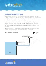
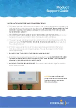
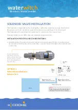
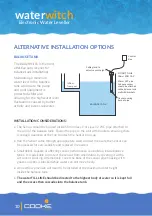
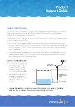
• The sensor requires a 50mm class 9 or class 12 PVC pipe to be installed as a balance line
from the project’s wall to the pump and filter area.
ALWAYS USE 50MM PIPE FOR THE
SENSOR HOUSING TO ENABLE ADEQUATE FLOW AROUND THE SENSOR AND
FUTURE SERVICABILITY.
•
THIS PIPE MUST BE PLACED AT LEAST 300MM BELOW WATER LEVEL
and can be
dressed with a push-in eyeball to match the project’s other wall fittings.
• The pipe is usually run along the suction and return trench and elbowed up within the
equipment area.
THIS PIPE MUST BE LEVEL TO AVOID AIR LOCKS
which will affect
flow and performance.
• A 50mm cap is provided to cover the sensor pipe housing and protect the Sensor
from dust, debris, pests and foreign materials. The cap fits neatly onto the 50mm
sensor pipe housing.
•
DO NOT GLUE THE CAP TO THE SENSOR HOUSING PIPE.
• If the Sensor is to be located away from the equipment area,
ALWAYS RUN THE LEAD
THROUGH ADEQUATELY SIZED CONDUIT THAT WILL ENABLE THE COMPLETE
SENSOR TO BE REPLACED AT A LATER DATE.
•
NEVER CUT EXCESS SENSOR CABLE.
Roll excess cable and bind together with the
Velcro straps provided.
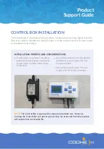
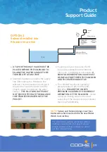
NOTE
:
Sensor and Solenoid
plugs must face backwards when
inserted into the new Water
Witch Control Box.


