SM-Encoder Plus & SM-Encoder Output Plus User Guide
15
Issue: 4
www.controltechniques.com
How to
S
Int
In
Sol
u
G
P
Diag
Te
Index
4.3.4
Cable requirements
All mounting methods:
•
Shield connection at drive terminal to 0V
•
Shield connection at encoder to 0V
•
It is recommended that the shielded cable should be run in a continuous length to
the terminal, to avoid the injection of noise at intermediate pigtails and to maximise
the shielding benefit.
•
The shield connections ("pigtails") to the drive and encoder should be kept as short
as possible
Mounting with no isolation:
•
Shield connected to ground at both ends. The connection must be made by direct
fixing of the cable to the grounded metal parts, i.e. to the encoder body and the
drive grounding bracket, as illustrated in Figure 4.9. "Pigtails" must be avoided. The
outer sheath of the cable should be stripped back enough to allow for the ground
clamp to be fitted. The shield connection should not be broken. The ground clamps
should be located as close as possible to the drive and encoder.
•
It is essential that the shielded cable should be run in a continuous length to the
terminal, to avoid the injection of noise at intermediate "pigtails" and to maximise the
shielding benefit.
Cable shield ground connection
For all mounting methods, grounding of the feedback cable shield has added benefits. It
can protect the drive and encoder from induced fast electrical transients, and prevent
radiated radio-frequency emission. However it is essential that it be carried out in the
correct manner as explained above and shown in Figure 4-9.
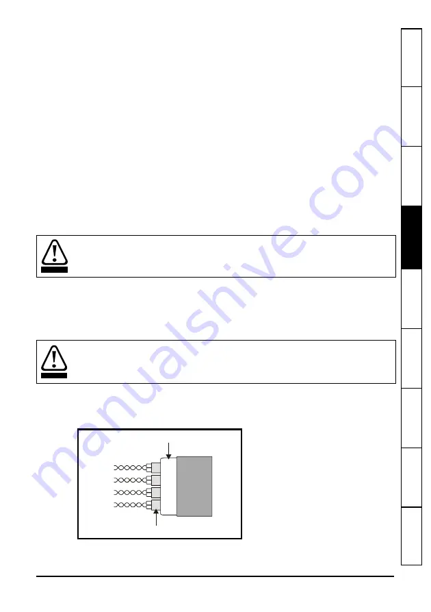
Recommended Cable
The recommended cable for feedback signals is a twisted pair, shielded with an overall
shield as shown below.
Figure 4-8 Feedback cable, twisted pair
Using this type of cable also allows for the connection of the outer shield to ground and
the inner shields to 0V alone at both drive and encoder end, when required.
In this case under no circumstances must the cable shield connection be omitted at
either end of the cable in this case, since the noise voltage may well be sufficient to
destroy the line driver and receiver chips in the encoder and the drive.
CAUTION
Connecting the cable shield to ground at both ends carries the risk that an electrical fault
might cause excessive power current to flow in the cable shield and overheat the cable.
There must be an adequately rated safety ground connection between the motor/
encoder and the drive.
WARNING
Twisted
pair
cable
Twisted pair shield
Cable
Cable overall shield
Содержание SM-Encoder Output Plus
Страница 42: ...0471 0026 04...


