Qualifier System
2-7
3.
CAUTION - DO NOT REVERSE WIRES IN THIS STEP!
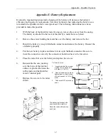
Connect the bare metal contacts on the 15-foot Transmitter Power Cable to the open side
of the fuse holders (see illustration).
•
Slide the
Red
wire with the bare contact into the empty hole on the fuse holder that
already has one Red wire installed. This is the Red wire that connects to the positive
battery terminal.
•
Slide the
Black
wire with the bare contact into the empty hole on the fuse holder that
already has one Black wire installed. This is the Black wire that connects to the
negative battery terminal.
4. Install a 15 Amp fuse in each of the two fuse holders. Install a cover over each fuse.
5. Make sure the Transmitter Power Switch is set to OFF. Connect the Antenna Cable to the
rear panel Antenna BNC Jack. Connect the Power Plug to the Transmitter rear panel
power Jack.
6. Set the Transmitter Power Switch to ON and check that only the POWER indicator
illuminates.
Test the Qualifier System Installation:
1.
Set the transmitter power switch to ON.
2.
Insert a two-inch length (approximate length) of small wire into the input connector on
the Qualifier meter. Use a small wire size to avoid damaging the input connector.
3.
Hold the Qualifier meter about ten feet from the service vehicle.
4.
Power the meter ON. (Charge the meter prior to performing this test, if needed.)
5.
Press the “Q” key to enable the meter’s Qualifier Mode.
6.
Press the “Q” key a second time to activate the transmitter and to initiate the
measurement sequence.
7.
The yellow TX light on the transmitter illuminates.
8.
The meter detects and displays a level of the test signal from the transmitter.
Note:
Insure the Receiver and Transmitter User Identifier (RUID) settings match. See the
System
Operation Section
for details.
Содержание CyberTek QUALIFIER
Страница 2: ......
Страница 8: ...Qualifier System iv This page intentionally left blank...
Страница 47: ......
Страница 48: ......


