Qualifier System
2-8
System Operation
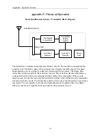
The transmitter is installed in the service vehicle (See section
Hardware Installation
).
The
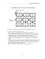
Qualifier meter activates the transmitter by using a radio frequency Command Link. A press
of the “Q” key turns on the Command Link, when the meter is in
Qualifier Mode.
This
allows the meter to remotely activate the transmitter. When the transmitter is actively
transmitting, a series of test signal bursts (at the factory pre-set frequency) are radiated at 5
watts from the antenna. If the test signal bursts ingress into the home, the Qualifier meter
verifies and measures the signal. It then displays an absolute or a relative level reading. (See
section
Qualifier meter
).
Qualifier Transmitter Details
Rear
Front
Receiver User Identifier (RUID) Rotary Switch
The ID Rotary switch has 0-F (16) possible values. This allows transmitter activation by
only a Qualifier meter that sends a particular identifier code in the command link. This
allows more than one Qualifier System to service a neighborhood without interference from
one another. The factory default setting is ‘0’.
Power Light (Green)
When powering the transmitter, this light will illuminate after the unit has finished internal
initialization and has determined that no current fault modes are active. If an over-
temperature fault condition is active, this light will not illuminate.
TX Light (Yellow)
When the transmitter is activated by a Qualifier meter, this light illuminates during the test
signal transmission to confirm the Command Link is functional and a test signal has been
generated.
VSWR Light (Red)
This light illuminates when there is an improperly matched antenna. In this fault condition,
this light only illuminates when the transmitter activates to generate a test signal. To correct
this fault, check the antenna and cycle the power.
Temperature Light (Red)
This light illuminates when the internal temperature of the transmitter exceeds the operating
limits. The transmitter shuts down in this condition and will not function until an acceptable
temperature is established. Maintain at least one inch of clearance around the transmitter for
proper cooling.
Содержание CyberTek QUALIFIER
Страница 2: ......
Страница 8: ...Qualifier System iv This page intentionally left blank...
Страница 47: ......
Страница 48: ......


