background image

Qualifier Meter

1-8

Making Measurements

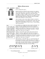
Each user request for a measurement causes the Qualifier meter to tune to the channel
assigned to the function key pressed: the Qualifier meter displays the picture carrier, and
another press of the same key toggles to the sound carrier, and subsequent keypresses toggle
back and forth between the two. First-time tuning may experience a slightly longer delay
than subsequent measurements as the Qualifier meter learns and stores the exact location of
the carriers within the channel. (This will happen once for each function key selection; it can
take place here or during the SETUP mode. See section 

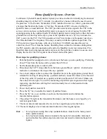
Quick-Tune Channels Define

.)

Several samples of the tuned channel peak amplitude are measured, averaged, augmented
with temperature and characteristic data particular to each instrument, and displayed. The
value is displayed as the Qualifier meter changes to a low power mode. Automatic power
down occurs if a key is not pressed for 1 minute. Repowering always furnishes the last
measurement made before power-down. The value will be blinking to serve as a reminder
that a previously measured value is being displayed.

                 is also active during normal measurement
operation; automatic power-down occurs if keys remain idle
for 1 minute.

During measurement mode, if the signal 

is less than

-30 dBmV

, the display substitutes 

LO

 for the signal level

readout. If the signal level is 

greater than 40 dBmV

, the

display substitutes 

HI

 for the signal level readout.

As an additional aid to verification of tuned signals, the Qualifier meter produces a low
impedance sound signal, provided through the earphone jack in the Qualifier meter’s case.
This sound signal is extracted by the Qualifier meter from sound, picture, digital, or other
carriers. When a channel is tuned by pressing an arrow key or one of the function keys,
sound can be heard through an earphone connected to the earphone jack. The sound is
turned on 15 seconds for video and 20 seconds for audio. (This is to preserve battery power.)

Signal level measurements are made by 

(a)

 powering-on the Qualifier meter, and

(b)

 selecting the channel to tune: first the picture carrier, then the sound carrier.

Содержание CyberTek QUALIFIER

Страница 1: ...ication templates in Microsoft Word and Acrobat formats along with helpful web sites to get you up and running in no time Please browse to and open the file named Customer Packet Read the Adobe Acroba...

Страница 2: ......

Страница 3: ...t 101268 001 Rev C unreleased H HO OM ME E Q QU UA AL LI IF FI IC CA AT TI IO ON N S SY YS ST TE EM M U Us se er r G Gu ui id de e Signal Level Meter with Digital Level Capability and Home Qualificati...

Страница 4: ...ely packed Please enclose information on the reason for return Ship the material prepaid All material in this manual is the property of ComSonics Inc and is protected under the United States copyright...

Страница 5: ...ardware Installation 2 2 System Operation 2 8 Qualifier Transmitter Details 2 8 Qualifier Meter Details 2 9 Appendix A Keypress Reference 3 1 Appendix B Channel Line Up Set and Country Set Codes 3 2 A...

Страница 6: ...ive for assistance in this matter CAUTION The Cybertek Home Qualifier System must be installed in a service vehicle equipped with a 12 volt negative ground electrical system Note The battery charger f...

Страница 7: ...r Mode Frequency 27 450 27 470 or 27 490 MHz Activation Distance Up to 150 feet between receiver and transmitter Power Battery User rechargeable 6 0 V 0 55 Ah Battery recharge life 550 measurements Si...

Страница 8: ...Qualifier System iv This page intentionally left blank...

Страница 9: ...o 860 MHz range It also has arrow keys for single step tuning the unit within this range There are keys to control the backlight feature as well as for powering the unit on and off The LCD features th...

Страница 10: ...ualifier metert and points To engage the contacts properly hold the Qualifier meter face up place the charger connector so the flanges fit into the corresponding grooves in the Qualifier meter s conta...

Страница 11: ...r a programmed digital channel Digital channels are user programmed via a computer program See section Feature Installation Utility 2 Battery symbol is illuminated if a battery low condition is sensed...

Страница 12: ...selected Country Set code number blinks Arrow keys step through the sets available see Appendix B for a complete listing Pressing F1 leaves this sequence and initiates the Units of Measure Define seq...

Страница 13: ...ailable country sets scrolls forward 1 to 25 with the standard configuration rolling over to the first set when the last set is passed scrolls backward rolling over to the last set when the first set...

Страница 14: ...red Value and the Bar Graph are suppressed from the display continued from previous page STEP KEYPRESS RESULTS The dBmV dB V display blinks indicating that this setting can be changed 4 Toggles betwee...

Страница 15: ...1 NOTE The display will blink if the channel has never been tuned before or is changed here if the channel has been previously tuned it will not blink 6 Change the channel setting Increments setting f...

Страница 16: ...ing always furnishes the last measurement made before power down The value will be blinking to serve as a reminder that a previously measured value is being displayed is also active during normal meas...

Страница 17: ...again displays the sound carrier of Channel 4 Similarly if the Qualifier meter displays the picture carrier for Channel 3 pressing displays the sound carrier of Channel 2 pressing yet again displays...

Страница 18: ...nel 3 pressing again displays the picture carrier of Channel 4 If the Qualifier meter displays the sound carrier for Channel 3 pressing displays the second audio carrier of Channel 3 pressing displays...

Страница 19: ...es automatic backlight deactivation and reactivation at strategic points during normal use Pressing the LIGHT key illuminates the backlight After 10 seconds the backlight automatically deactivates Aft...

Страница 20: ...e CyberTek Home Qualification System specifically the transmitter component Contact your ComSonics representative for assistance in this matter CAUTION The Cybertek Home Qualifier System must be insta...

Страница 21: ...Basic steps for qualifying a home 1 Park the Qualifier equipped service vehicle near the home you are qualifying Preferably about 75 feet from the home and no greater than 150 feet 2 Set the transmit...

Страница 22: ...use Use the hardware supplied with the system Transmitter Powering Cable The cable assembly is approximately 16 feet long and connects the transmitter to the vehicle battery The cable has two sections...

Страница 23: ...the roof to the point where the antenna cable will enter the vehicle Coil any excess cable in a loose loop inside the vehicle Secure the cable as necessary Prepare to Install the Transmitter Check th...

Страница 24: ...e transmitter with mounting bracket over the selected mounting location Allow at least 1 inch beyond the rear end of the bracket for installation of cables Mark the location of the four mounting holes...

Страница 25: ...r punch Remove any paint from the area of the hole to provide a good electrical connection between the ground lug and the vehicle chassis 7 Use a 1 4 inch nut driver attached to a power screwdriver or...

Страница 26: ...hen disconnecting battery cables in a vehicle Remove the Negative black battery terminal first Then remove the Positive red battery terminal last Reconnect the Positive red terminal first and the Nega...

Страница 27: ...C Jack Connect the Power Plug to the Transmitter rear panel power Jack 6 Set the Transmitter Power Switch to ON and check that only the POWER indicator illuminates Test the Qualifier System Installati...

Страница 28: ...n one Qualifier System to service a neighborhood without interference from one another The factory default setting is 0 Power Light Green When powering the transmitter this light will illuminate after...

Страница 29: ...ents to identify the transmitter s test signal It then displays the level measurement and a relative percentage reading based on the threshold value F1 Key Toggles Automatic Manual Press the F1 key to...

Страница 30: ...and transmitters used in conjunction must have their frequencies match for the Qualifier System to function properly F6 Key Exit Press the F6 key to exit Qualifier Mode and restore standard signal lev...

Страница 31: ...unes to the picture carrier of the current channel Toggles LCD backlight on and off Activates SETUP mode Changes Country Set Changes Units of Measure Changes Quick Tune channel settings Activates Qual...

Страница 32: ...eden 22 Switzerland 23 Taiwan 24 United Kingdom 1 25 United Kingdom 2 Country Set Codes 1 through 25 are included in the Feature Installation Utility as factory default channel groups Use the utility...

Страница 33: ...tomatically start If the PC auto start function is turned off follow the instructions below to manually install the program Manual Install Click Start then click Run Type D SETUP If your CD ROM drive...

Страница 34: ...r System 3 4 Modify the Channel Group From the Edit Menu or by use of the Command Buttons select and modify these properties Group Information Function Key Quick Tune Channels Add Channel Delete Chann...

Страница 35: ...aining digital channel descriptions more than 128 channels or analog dB offsets will not load into non digital units Modify Group List From the Tools Menu select Modify Group List Select the group to...

Страница 36: ...m sea level to a very high elevation may cause air pockets within the keypad To alleviate this the Qualifier meter is fitted with a pressure relief valve a Phillips screw directly beneath the label on...

Страница 37: ...Methode connector and remove the battery Discard the old battery properly 4 Put the new battery in place and attach its two pin Methode connector Be sure to insert the connector correctly the connecto...

Страница 38: ...tion receiver The activation decoder determines a code match between the received signal and the setting of the transmitter When a code match occurs the decoder activates the transmitter enable switch...

Страница 39: ...transmitter receives the activation signal and verifies the coding If the coding matches the vehicle transmitter powers on and radiates the home with a test signal The input tuner section receives the...

Страница 40: ...rom the ground and secured to the home The drop cable is routed down the side of the home to a device called a ground block The ground block is a pass through device connected to an earth ground It is...

Страница 41: ...am path is vulnerable to the effects from devices that radiate electrical energy in the 5 to 50 MHz frequency range The upstream path uses digital signals and as such is subject to very unreliable ope...

Страница 42: ...the internal cabling is susceptible to ingress from devices within the home then it will also have ingress from a known signal source The known signal source is a mobile transmitter operating on a fr...

Страница 43: ...ing integrity of the cabling within the home is acceptable Test signal level measurements may be indicated by the receiver in common units of measurement such as V or dBmV The receiver may automatical...

Страница 44: ...The level of the received test signal is compared to a reference standard to determine if the shielding integrity of the drop cable is acceptable Test signal level measurements may be indicated by th...

Страница 45: ...iminated A multitude of activation codes is available allowing multiple test systems to be in operation in the same vicinity Only the transmitter associated with a given receiver code activates when n...

Страница 46: ...s declaration relates is in conformity with the provisions of Council Directive 89 336 EEC May 3 1989 on Electromagnetic Compatibility as amended by Council Directive 92 31 EEC April 28 1992 and Counc...

Страница 47: ......

Страница 48: ......

Отзывы: