Appendix - Qualifier System
3-9
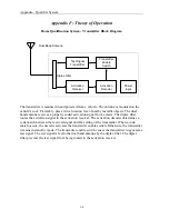
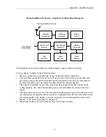
Home Qualification System - Signal Level Meter Block Diagram
The Qualifier meter is powered by an internal battery and is portable in design.
A test sequence consists of the following steps:
•
Meter is connected to ground block or tap / pedestal of home under test.
•
User interface operation turns on the activate encoder. The activate encoder has been
previously setup to match the intended vehicle transmitter. The activate transmitter is
powered on and the activate signal is radiated from the internal antenna.
•
The vehicle transmitter receives the activation signal and verifies the coding. If the
coding matches, the vehicle transmitter powers on and radiates the home with a test
signal.
•
The input tuner section receives the test signal resulting from ingress into the home. The
test signal detector qualifies the test signal as originating from the test transmitter. If the
test signal qualifies, the display converter sends the level measurements to the visual
display. A ‘Q’ factor percentage is displayed.
•
Measurement data is stored to data memory by the user interface.
Internal Activate Antenna
Visual
Display
Input Tuner
Section
Activate
Transmitter
Activate
Encoder
Battery
Power
Test Signal
Connection
Test Signal
Detector
Data
Memory
Display
Converter
User
Interface
Содержание CyberTek QUALIFIER
Страница 2: ......
Страница 8: ...Qualifier System iv This page intentionally left blank...
Страница 47: ......
Страница 48: ......


