background image


Page 

50

 of 

73


VastraJet K2 

 9. SWITCH OFF PROCEDURE 

Note:

 The machine main power must be 

ON

Follow these steps to learn the switch off procedure:  

Step 1:

 Perform the Nozzle Test to check print head nozzles status. 

Step 2:

 Up the press roller (using the back HMI) and remove the fabric.  

Step 3: 

Clean the Capping Station area and check the water level in the Capping tray.  

Step 4: 

Click the 

Auto Capping

 icon to engage capping station with the head plate using the Printer Manager, as 

shown below:


Fig 65: Displaying the Auto Capping Option 

Note:

 Never move the carriage manually over elevated capping station. 

Step 5:

 Close the printer manager software.  

Step 6:

 Turn OFF the Print Engine from the front HMI using the SERVICE screen. 

Step 7:

 Turn OFF the printer using the Machine Power button or Emergency button. 

Step 8:

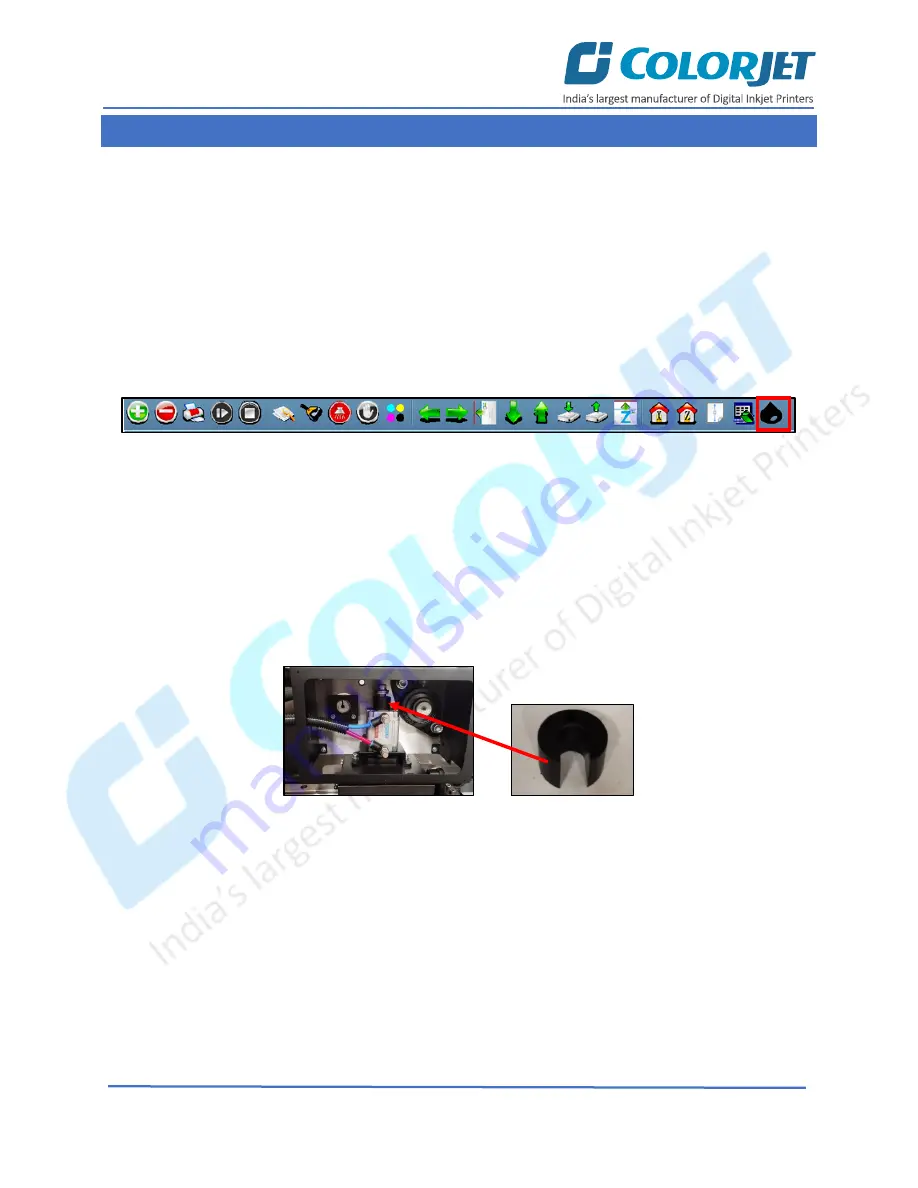
 Insert the bracket to hold the press roller in the UP position, as shown below:  


Fig 66: Holding the Press Roller in the Up Position


Step 9:

 Cover the printer to avoid dust particles on the machine parts.  

Now, the printer is switch off. 


Содержание VASTRAJET K2

Страница 1: ......

Страница 2: ...chine without anyone else assistance The information provided in this document ensures its uniqueness and language quality For safe and proper use of the product please read this manual carefully and...

Страница 3: ...he Fabric 14 Refilling Ink 16 5 HMI Operations 17 Control Panel Operational flow diagram 17 Main Menu Front HMI 20 Purging Ink 21 Service Screen 22 Controlling Belt Movement 22 Setting Belt Speed 23 S...

Страница 4: ...Wiping 47 Setting Wiping and Capping Height 48 Head Purging 48 Head Spraying 49 9 Switch OFF Procedure 50 10 Glue Coating 51 Glue Implementation 51 Glue Process Preparation 52 11 Do s and Don t 59 12...

Страница 5: ...the terminologies of printer and printing business Thus this document is designed to facilitate both types of users VastraJet K2 Printing Technology Drop on demand Piezo Electric Inkjet Print Heads I...

Страница 6: ...VERVIEW FRONT VIEW The Front View of the machine is shown in the image below Fig 1 Displaying the Front View of the Machine Right Cover Monitor Tower Light Right Cover Washing Unit Keyboard Stand Fron...

Страница 7: ...Page 6 of 73 VastraJet K2 BACK VIEW The Back View of the machine is shown in the image below Fig 2 Displaying the Back View of the Machine...

Страница 8: ...image below Fig 3 Displaying the Feeder Unit The Roller Adjustment Handle and Supply Shaft are shown in the image below Fig 4 Displaying Different Parts of the Feeder TRUSS SPREADER ROLLER Banana ROLL...

Страница 9: ...is shown in the image below Fig 5 Displaying THE Different Parts of the Dryer The top view of the Dryer is shown in the image below Fig 6 Displaying the Back View of the Dryer GUIDE ROLLER EXHAUST PI...

Страница 10: ...moving the tub Up or Down Press roller Help in changing the position Up or Down Soaking roller Help in changing the position Up or Down Dancing roller Help in dancing the roller Note Air pressure rate...

Страница 11: ...ize it After that the carriage comes back to the Z print position Finally the Wiper unit gets activated and starts the initialization process Step 6 Check the negative pressure range 4 2 to 4 6 Step 7...

Страница 12: ...n the paper by issuing the Nozzle Test command If nozzle test result is not OK or nozzles are blocked perform the head wiping and purging Step 13 Go Online from the front HMI to enable the ONLINE mode...

Страница 13: ...Load the fabric and engage the press roller Refer to the Loading Fabric section Note Please be careful while loading the fabric as there are chances of serious injuries like pinching finger or hand S...

Страница 14: ...is given as below Color Light of Steadily Flashing Light Remarks Red Emergency System Error Need to Restart Orange Printer is Working Printer in working mode Green Printer is ON Blue Printer is ON The...

Страница 15: ...of Safety Chuk and Shaft get matched as shown below Fig 14 Displaying the Unlock Position Step 3 Push the Safety Chuk to remove the shaft Step 4 Insert the shaft into the fabric roll Step 5 After ins...

Страница 16: ...d the fabric as per the path given below Fig 17 Displaying the Fabric Path Note Please be careful while loading the fabric as there are chances of serious injuries like pinching finger or hand Step 8...

Страница 17: ...fill ink as per the color sticker The Main Ink Tank is shown in the image below Fig 18 Displaying the Main Ink Tank Note Don t shake ink bottles The Ink Sub Tank is shown in the image below Fig 19 Dis...

Страница 18: ...HMI is shown as below WASHING SYSTEM SET P DRYER 2 C TEMP P DRYER 2 C TEMP ALARM INK PURGING SERVICE READY TO PRINT BELT MOVEMENT MAIN ON LINE INK PURGING BUTTONS INK CIRCULATION BUTTONS PRINT ENGINE...

Страница 19: ...traJet K2 Continue WASHING SYSTEM SET BRUSH OFF TUB OUT PRINT DRYER OFF BELT DRYER OFF JETTING PUMP OFF BELT MOVEMENT ON LINE AUTO REV AUTO FWD MANUAL REV MANUAL FWD SPEED PRINT STOP START RESUME READ...

Страница 20: ...Operational flow diagram is shown in the image below PRESS ROLL HIGH POS PRESS MOVEMENT SOAKING ROLLER LOW POS BELT MOVEMENT BACK HMI PRESS ROLL LOW POS SOAKING ROLLER LOW POS AUTO REV FWD MANUAL REV...

Страница 21: ...settings and turn on the washing system ALARM Turn ON or OFF the alarm unit BELT MOVEMENT Move the belt in reverse or forward direction with different modes viz Auto and Manual Service Turn ON or OFF...

Страница 22: ...e nozzles To purge ink from print head touch the MAIN MENU INK PURGING screens The INK PURGING screen is shown in the image below Fig 21 Displaying the INK PURGING Screen In the above screen user can...

Страница 23: ...s shown in the image below Fig 22 Displaying the SERVICE Screen Note Please don t disturb the above shown settings refer to Fig 22 as this part is mainly used by the service engineer CONTROLLING BELT...

Страница 24: ...lt in the forward direction MANUAL REV Manually move the belt in the reverse direction MANUAL FWD Manually move the belt in the forward direction SETTING BELT SPEED To set the belt speed touch the SPE...

Страница 25: ...aying the WASHING UNIT Screen The description of different options in the WASHING SYSTEM screen is given as follow BRUSH OFF Turn ON or OFF the brush unit BELT DRYER Turn ON or OFF the belt dryer TUB...

Страница 26: ...Refer to Fig 20 The READY TO PRINT screen appears as shown below Fig 26 Displaying the HEATERS SETTINGS Screen Note Default dryer settings are fed User can update the dryer temperature setting as per...

Страница 27: ...touching the ONLINE icon on the Main Menu screen the following screen appears Fig 27 Displaying the ONLINE Mode Screen Using the above screen user can also open the READY TO PRINT screen simply by to...

Страница 28: ...Soaking Roller Low Pos Set the soaking roller position Low or High Belt Movement Set the belt movement auto manual and rev fwd refer to Fig 23 Case 1 On click the Press Roll Low Pos and Soaking Rolle...

Страница 29: ...more frequently like Add Job Delete Job Print Job Pause or resume Abort job Check nozzle Move left Move right Move forward Move backward Z Move Down Z Move Up Move carriage to origin and more Job Info...

Страница 30: ...Page 29 of 73 VastraJet K2 SETTING MENU The Setting window with the Printer tab is shown in the below image Fig 30 Displaying the Setting Window...

Страница 31: ...t K2 The Move tab is shown in the image below Fig 31 Displaying the Move Tab The Preference Tab is shown in the image below Fig 32 Displaying the Preference Tab Note Unit value can be changed using th...

Страница 32: ...Step 1 Click on the Main Menu Tools Password options as shown below Fig 33 Selecting the Password Option The Password window appears on the screen as shown below Fig 34 Displaying the Password Window...

Страница 33: ...Page 32 of 73 VastraJet K2 Note When First Warning appears kindly contact Head Office with the following screen Password Screen Refer to Fig 34 About Screen Fig 35 Displaying the About Screen...

Страница 34: ...start the printing by clicking on the left and right buttons on the Quick Access Toolbar as shown below Fig 36 Adjusting the Carriage Position Step 2 After positioning the carriage click on the Set p...

Страница 35: ...Z Parameter screen appears as shown below Fig 40 Setting the Print Head Height A default value of media fabric thickness is 3 89 for 0 1 1 0 mm fabric In case the fabric thickness gets changed then us...

Страница 36: ...e mentioned checks and calibration one by one in details Note Mechanical checks are performed by service engineer thus these checks and their description are not included in the user manual NOZZLE CHE...

Страница 37: ...e Main Menu Tools Calibration Wizard options as shown below Fig 43 Selecting the Calibration Wizard Option The Calibration Home Page screen appears Click the Next button and user redirects to the Mech...

Страница 38: ...Page 37 of 73 VastraJet K2 When the Next button is pressed you are redirected to the software calibration screen as shown in the below images Fig 45 Displaying the Printer Calibration Options...

Страница 39: ...ct the Left to Right test print would align accurately with the Right to Left test print at 0 position In case of error in the Bi Direction offset the Left to Right and Right to Left print would align...

Страница 40: ...left sweep When the position of the test head is correct then it would align perfectly with the reference color at 0 position indicating that the error position is 0 If the test print head s position...

Страница 41: ...ration From the above figure you get the accurate step adjust correction value The correction value is either positive or negative If the value is positive then add it in the current step adjust value...

Страница 42: ...rrors in the current print job by specifying number of steps Pass Choose the number of passes with which the print job should be printed Increasing the number of passes improves the print quality but...

Страница 43: ...Step 3 Click on the Open button to add the file into the Job List area as shown below Fig 52 Adding the Job Now the selected image appears in the Job List area as shown below Fig 53 Displaying the Ad...

Страница 44: ...e job icon on the Quick Access Toolbar EDITING JOB Follow these steps to edit the selected job Step 1 Select the job for which details you want to edit from the Job List area Step 2 Right click on the...

Страница 45: ...e image can be selected by dragging the image preview User can also adjust height and width using the above window Tile By enabling this desired number of counts in x and y directions can be printed U...

Страница 46: ...nd While ripping the color profiles are used to automatically perform the color corrections in the image You can print an image on the selected fabric simply by clicking on the Print Job button availa...

Страница 47: ...ting job using the Pause or resume and Abort Job buttons available on the Quick Access Toolbar as shown below Fig 59 Issuing the Pause or resume Command Similarly you can abort the process by right cl...

Страница 48: ...The Auto Wiping option is shown in the image below Fig 60 Displaying the Auto Wiping Option On clicking the Auto Wiping icon the Manual Clean Form window appears on the screen as shown below Fig 61 D...

Страница 49: ...and Z Wet Pos list boxes as shown below Fig 62 Setting Wiping and Capping Height HEAD PURGING Head purging refers to the method in which heads are cleaned by forcing pressurized ink through the nozzl...

Страница 50: ...mixing of colors during the head purging and wiping process This method can help to open head nozzles if few nozzles are blocked To perform head spraying click on the Spray button available under the...

Страница 51: ...station with the head plate using the Printer Manager as shown below Fig 65 Displaying the Auto Capping Option Note Never move the carriage manually over elevated capping station Step 5 Close the prin...

Страница 52: ...to dilute the adhesives or to complete removal of the all adhesive layers The following are the two main reasons for removing all the glue layers When the thickness of the adhesive layer goes on incre...

Страница 53: ...Aromatic Benzene Toluene Xylene Aliphatic Hexane Cyclohexane Ketone Acetone NOT RECOMMENDED Methyl ethyl ketone MEK Chlorinated hydrocarbon Methyl chloride Mono chlorbenzene Chloroform Trichloroethane...

Страница 54: ...mode using the BELT MOVEMENT screen Step 4 Put masking PVC tape on both edges of the Conveyor Belt by simultaneously moving the belt through HMI in slow speed Fig 68 Using Masking Tape Step 5 Put on g...

Страница 55: ...ess Follow these steps to start the glue coating process Step 1 Before starting the glue coating make sure that tub is out In case tub is not out touch the TUB IN icon on the WASHING SYSTEM screen to...

Страница 56: ...n the reverse direction with slow speed using the BELT MOVEMENT screen as shown below Fig 72 Setting the Belt Speed Note Belt speed should be 8 Step 4 Pour 70 glue equally in front of the Glue Applica...

Страница 57: ...cleaner liquid continuously till the end Fig 74 Spraying the Cleaner Liquid Step 9 Later the cleaner liquid spraying should be done throughout the belt until the remaining glue appears to be deactivat...

Страница 58: ...ss Additionally glue or the cleaner may damage the brush roller or sponge roller thus put a cover on the washing unit GLUE REMOVING PROCEDURE Glue coat gets damaged due to several reasons like during...

Страница 59: ...over all Fig 77 Wiping the Glue Step 7 Spray or pour purified water onto the belt Step 8 Wipe out cleaner on the belt by paper towel Fig 78 Wiping Out Cleaner from the Belt Step 9 After clean up the p...

Страница 60: ...thickness option Also check the bi direction calibration 13 Always care about the wrinkles on fabric it may damage the print heads 14 Conveyor belt shifting has to be monitored regularly 15 Always us...

Страница 61: ...should be clean Degassing pressure has to be monitored regularly and it should be in between 85 to 95 KPa In case degassing pressure is not maintained then it may cause the nozzle blockage If thickne...

Страница 62: ...he belt in the reverse direction using the Belt Movement icon from HMI until it comes in the center ii Adjust the Belt Adjustment screws refer to the upcoming section for more details iii After adjust...

Страница 63: ...shown below Fig 80 Removing the Side Cover Step 2 Loose both the screws available on the top of the belt adjustment handle Note While performing the belt shifting control process user needs patience a...

Страница 64: ...1 and case 2 one by one Case 1 Belt is Shifting Left Side from the Back As per the above figure belt is shifting toward the left side from back of the machine In this case user needs to loose screw 2...

Страница 65: ...n this case user needs to loose screw 1 and then tight screw 2 as per the requirement After adjusting the belt shifting move the belt and carefully observe the belt movement Fig 83 Controlling Belt Sh...

Страница 66: ...wash cycle after finishing each fabric roll and also remove the fabric thread if any Clean the purging tray daily Maintain the recommended air pressure Belt shifting should regularly be monitored and...

Страница 67: ...for Maintenance Step 1 Lower down the tub by following the screens Main Menu Washing System Set Tub IN as shown below Fig 84 Displaying the Washing System Screen Step 2 Remove Allen screws from both s...

Страница 68: ...rush to remove fabric threads and thoroughly wash with water to remove Glue residue layer on it Sponge rollers should be rinsed with water and squeezed simultaneously Check the jetting pump for any ch...

Страница 69: ...iles from your computer to maintain a free space Remove unwanted programs and old ripped files from the computer to improve the speed of printing MONTHLY MAINTENANCE LM guide should be wiped monthly C...

Страница 70: ...s distorted Glue dryer is OFF BELT SHIFTED Shifting is not monitored and arrested properly using the belt adjustment handle Belt Shifting Adjustment screw is tighten loosen incorrectly or excessive NE...

Страница 71: ...bar weight is less Core is slipping and not intact with air shaft Fabric is not stick to the core IMPRESSION OF INK ON PLAIN FABRIC Belt is not washed properly Water in the tank is dirty and have fabr...

Страница 72: ...Fiber optical cable is faulty LVDS is faulty PRINT IS BLUR No proper calibration viz bi direction and step Head height is disturbed and not calibrated Incorrect resolution is selected X div is select...

Страница 73: ......

Страница 74: ...For Any Query Please Contact Us www colorjetgroup com Call us on 91 120 4548195 Email on info colorjetgroup com For Ink Enquiry sales colorjetgroup com...

Отзывы: