BBG1070QS-OM (V1.8)
BBG-1070-QS PRODUCT MANUAL
3-11
Setup/Operating Instructions
BBG-1070-QS Function Menu List and Descriptions
(continued)
• Cascade Mode Select
Cascade Mode Select
Note: • See Cascading (Multi-Device) BBG-1070-QS Operation and
Setup Overview (p. 1-8) in Chapter 1, Introduction for an overview
of multi-unit cascading that provides multiviewer images
exceeding that of a single quint-split unit.
• See Cascade Mode Using PiP Layout QuickSet Template Presets
(p. 3-16) for examples control settings using Cascade Mode along
with other per-PiP settings to provide a cascaded multiviewer
image setup.
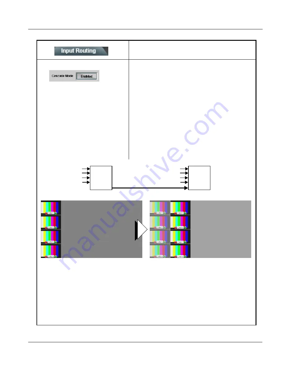
Cascade Mode Select sets PiP 5 as a input to be used to receive a
cascade output from another BBG-1070-QS unit or to be set as a regular
fifth PiP input as follows:
• Enabled: Sets PiP 5 input to receive a cascade output from another
BBG-1070-QS unit. Because this cascaded underlay will have any
burn-in insertions already in place from the upstream source unit, all
PiP 5 burn-in insertions are automatically disabled in this mode.
Also, since this PiP will serve as an underlay for any added PiPs, in
this mode PiP 5 is inserted full-size, with all sizing and positioning
controls locked out for this PiP insertion.
• Disabled: Sets PiP 5 input to be used as regular input, with full
aspect and sizing/positioning control and burn-ins as PiPs 1 thru 4.
Use this mode when only a single, non-cascaded BBG-1070-QS is
to used for multi-image processing.
Table 3-1
BBG-1070-QS Function Menu List — continued
PiP 1 IN (“CAM 1”)
PiP 2 IN (“CAM 2”)
PiP 3 IN (“CAM 3”)
PiP 4 IN (“CAM 4”)
BBG-QS
“UMD 1”
thru
“UMD 4”
BBG-QS
“UMD 5”
thru
“UMD 8
+ Cascade
Cascade
PiP 1 IN (“CAM 5”)
PiP 2 IN (“CAM 6”)
PiP 3 IN (“CAM 7”)
PiP 4 IN (“CAM 8”)
First BBG-1070-QS receives “CAM 1” thru “CAM 4”, as
PiP 1 thru PiP 4 inputs. This output is fed to a second,
daisy-chained BBG-1070-QS as a cascading input.
The second BBG-1070-QS receives “CAM 5” thru “CAM 8”, as
PiP 1 thru PiP 4 inputs and is set to position these images in a
2nd column. The imported PiP 5 cascade input (carrying
“CAM 1” thru “CAM 4”) serves as an underlay.
The resulting output (consisting of eight PiPs) now consists of
the imported cascading “CAM 1” thru “CAM 4” images, as well
as the local input “CAM 5” thru CAM 8” images.
Note: When using cascade mode, the symmetrical alignments shown here are available as “QuickSet” presets using the per-PiP
controls as described in PIP Layout Controls (p. 3-14) and in the example shown in Cascade Mode Using PiP Layout QuickSet
Template Presets (p. 3-16).
Содержание BBG-1070-QS
Страница 90: ...3 68 BBG 1070 QS PRODUCT MANUAL BBG1070QS OM V1 8 This page intentionally blank...
Страница 91: ......


