background image

3

Control and Display Descriptions

3-4

BBG-1002-2UDX PRODUCT MANUAL

BBG-1002-2UDX-OM (V1.3)

Finding a BBG-1002-2UDX Device in DashBoard

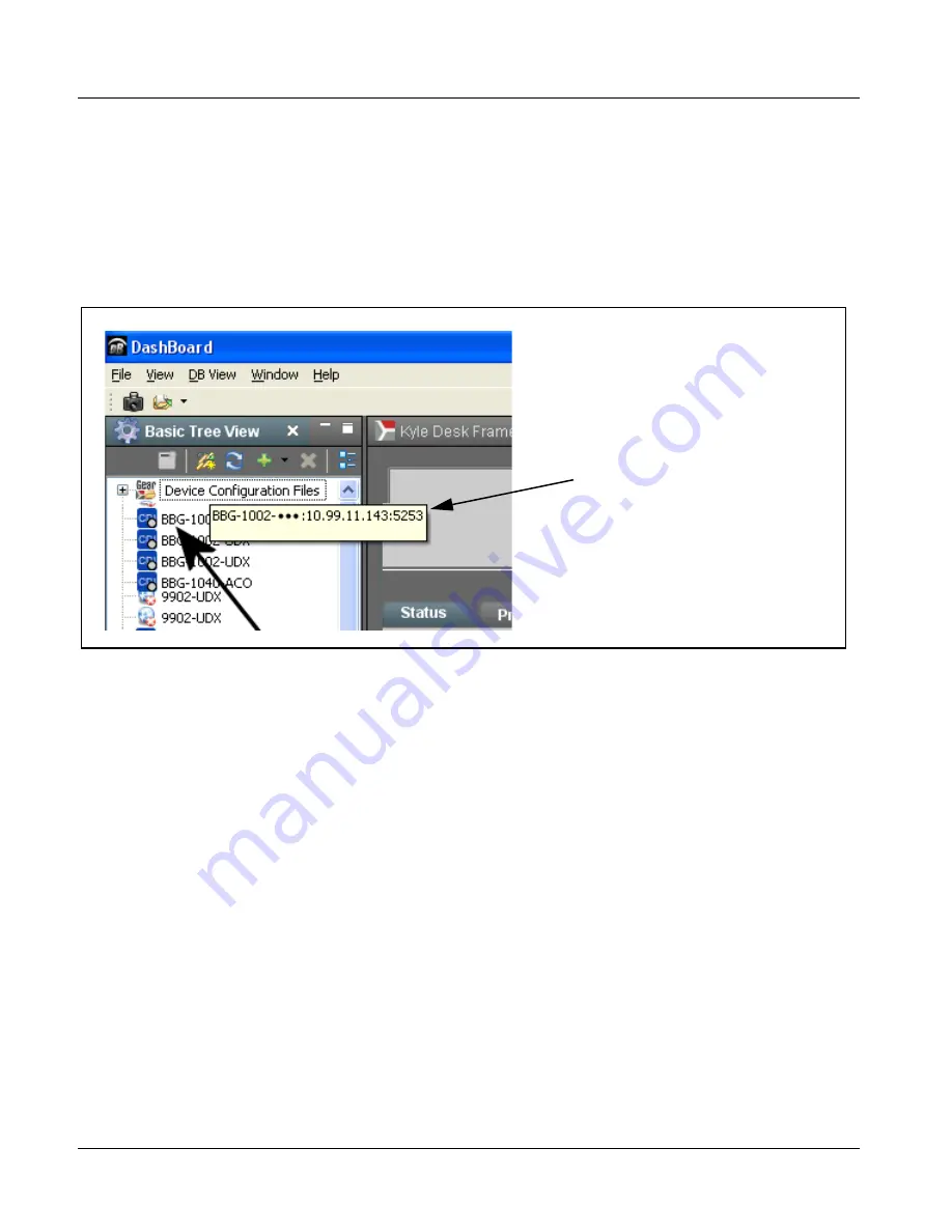
(See Figure 3-2) If BBG-1002-2UDX is configured with an address within a 
network also available via DashBoard, a BBG-1002-2UDX device appears as 
a frame entity in the DashBoard Basic Tree View.

Note:

BBG-1002-2UDX DashBoard remote control is also available by opening the 
device in DashBoard similar to opening an openGear

®

 card.

Figure 3-2  Finding BBG-1002-2UDX Using DashBoard

Control and Display Descriptions

This section describes the user interface controls, indicators, and displays for 
using the BBG-1002-2UDX. The BBG-1002-2UDX functions can be 
accessed and controlled using any of the user interfaces described here.

The format in which the BBG-1002-2UDX functional controls, indicators, 
and displays appear and are used varies depending on the user interface being 
used. Regardless of the user interface being used, access to the 
BBG-1002-2UDX functions (and the controls, indicators, and displays related 
to a particular function) follows a general arrangement of Function Menus 
under which related controls can be accessed (as described in Function Menu/
Parameter Overview b
elow).

Note:

When a setting is changed, settings displayed on DashBoard™ (or a Remote 
Control Panel) are the settings as effected by the device itself and reported 
back to the remote control; the value displayed at any time is the actual value 
as set on the device.

Hovering over the blue BBG icon in 
DashBoard displays the address of the BBG 
device

Содержание BBG-1002-2UDX

Страница 1: ...Voice 217 344 1243 Fax 217 344 1245 www cobaltdigital com Product Manual BBG 1002 2UDX OM V1 3 Cobalt Digital Inc 3G HD SD SDI Standalone Dual Channel Up Down Cross Converter Frame Sync Audio Embed D...

Страница 2: ...ademark of Cobalt Digital Inc openGear is a registered trademark of Ross Video Limited DashBoard is a trademark of Ross Video Limited Dolby is a registered trademark of Dolby Laboratories Inc Other pr...

Страница 3: ...1 14 Warranty and Service Information 1 19 Cobalt Digital Inc Limited Warranty 1 19 Contact Cobalt Digital Inc 1 20 Chapter 2 Installation 2 1 Overview 2 1 Installing the BBG 1002 2UDX 2 1 Installing...

Страница 4: ...trols 3 33 Timecode 3 38 Reticules 3 43 Wings Insertion 3 46 AFDProcessor Controls 3 47 Moving Box Insertion 3 53 Ancillary Data Proc Controls 3 55 COMM Ports Setup Controls 3 58 Presets 3 60 GPO Setu...

Страница 5: ...r 2 Installation Provides instructions for installing the BBG 1002 2UDX in a frame and optionally installing a BBG 1002 2UDX Rear I O Module Chapter 3 Operating Instructions Provides overviews of oper...

Страница 6: ...imilar 20 slot frame that houses Cobalt or other cards Device and or Card refers to a Cobalt or other card System and or Video System refers to the mix of interconnected production and terminal equipm...

Страница 7: ...ovide supplemental information to the accompanying text Notes typically precede the text to which they apply Labeling Symbol Definitions Important note regarding product usage Failure to observe may r...

Страница 8: ...ortant safety instructions regarding the proper installation and safe operation of the frame as well as its component products CAUTION The BBG 1002 2UDX FPGA is designed for a normal range operating t...

Страница 9: ...sed timecode formats and CEA608 708 HD formats to HD ATC SD_ATC and SD VITC waveform based timecode BBG 1002 2UDX Input Output Formats The BBG 1002 2UDX provides the following inputs and outputs which...

Страница 10: ...eo Quality Events Check UDX Convert ARC AFD Deserialize Timecode Select Proc Video Quality Events Check To Path 1 2 Audio Embed From Path 1 2 Audio De Embed Path 1 Path 2 HANC VANC ANC Extract Insert...

Страница 11: ...e unit when selected as a choice on the output crosspoint Option QC Quality Check allows criteria such as black frozen frame events to propagate an event alert This alert can be used by the Presets fu...

Страница 12: ...e output can be set to disable video go to black go to an internal test signal generator pattern or freeze to the last intact frame last frame having valid SAV and EAV codes An internal test signal ge...

Страница 13: ...YCbCr SDI on the output Controls are available to adjust each RGB level independently for both white levels gain and black levels offset Gamma can also be independently adjusted for each RGB channels...

Страница 14: ...as a processed video output Audio Processor Description Note Path 1 and Path 2 have individual independent digital audio embed and de embed banks for each of the processing path s 16 channels of embe...

Страница 15: ...nput selection to be changed from one source to another while ducking audio during controlled input video switching transitions to provide silence between input switches The cross fade is queued for t...

Страница 16: ...h 1 and Path 2 embedded internal Audio Bus sources to the Path 1 and Path 2 discrete output audio crosspoints Text To Speech Cobalt Digital TTS is a complete 21CVAA digital text to speech generation a...

Страница 17: ...ined Invoking a user preset to effect a change involves setup communication limited only to the items being changed the unit remains on line during the setup and the called preset is rapidly applied G...

Страница 18: ...set to monitor input video audio for input errors such as input LOS frozen or black frame loss of reference closed captioning ancillary data loss and or per channel audio absences These alarms can be...

Страница 19: ...Supply BBG 1002 2UDX D DIN 4 3G HD SD SDI Inputs 4 Balanced Analog Audio Inputs 4 AES Inputs 4 3G HD SDI Outputs 4 AES Outputs 4 Balanced Analog Audio Outputs 1 CVBS Input 1 CVBS Output All coaxial c...

Страница 20: ...o MDIX via HTML5 web interface Front Panel Controls and Indicators Backlit LCD display and menu navigation keys Display and controls provide unit status display and full control as an alternate to web...

Страница 21: ...BNC Impedance 75 Return Loss 15 dB at 5 MHz 270 MHz Post Processor Serial Digital Video Outputs cont Signal Level 800 mV 10 DC Offset 0 V 50 mV Jitter 3G HD SD 0 3 0 2 0 2 UI Minimum Latency scaler an...

Страница 22: ...e Reference Input Looping 2 BNC connection SMPTE 170M 318M Black Burst SMPTE 274M 296M Tri Level Return Loss 35 dB up to 5 75 MHz GPIO 2 GPI 2 GPO opto isolated GPO Specifications Max I 120 mA Max V 3...

Страница 23: ...gistering the product by completing and returning a product registration form In the event of a warrantable defect the purchaser shall notify Cobalt with a description of the problem and Cobalt shall...

Страница 24: ...rough and professional support representatives for any of the following Name and address of your local dealer Product information and pricing Technical support Upcoming trade show information Phone 21...

Страница 25: ...BG 1002 2UDX in locations marked with stamped x If feet are not affixed chassis bottom cooling vents will be obscured Where BBG 1002 2UDX is to be installed with optional frame Mounting Tray BBG 1000...

Страница 26: ...UDX coaxial inputs are internally 75 ohm terminated It is not necessary to terminate unused BNC video inputs or outputs External frame sync reference signal if used must be terminated if a looping dai...

Страница 27: ...1002 2UDX Dimensional Details 1 73 15 26 1 75 FEET REMOVABLE FEET 4 PLACES 14 30 5 80 1 65 FRONT REAR TOP Notes 1 All dimensions in inches 2 If BBG 1002 is mounted on flat surface either rubber feet m...

Страница 28: ...l DC power IN connectors diode isolated Single AC adapter supplied can be connected to either connector Dual adapters can be connected to provide power redundancy 10 100 1000 ETHERNET Gigabit Ethernet...

Страница 29: ...O and Analog Audio Connector Pinouts G Removable Phoenix plug view oriented with top screw terminals up Note Unbalanced connections can be connected across the and G terminals Note that this connectio...

Страница 30: ...uivalent opto isolated circuits shown below GPO GPO COM GPI 10 k 3 3V GPO from card control GPI to card control V GPO Specifications Max I 120 mA Max V 30 V Max P 120 mW Pullup R 500 resistor is recom...

Страница 31: ...Number Locations and Ranges p 3 9 BBG 1002 2UDX Function Menu List and Descriptions p 3 10 Uploading Firmware Using Web Interface and GUI p 3 74 Troubleshooting p 3 75 BBG 1002 2UDX Front Panel Displ...

Страница 32: ...now access and enter the menu item When this button is pressed the selected menu item is displayed along with its sub menus In this example showing the Network Settings menu Menu Network Settings as m...

Страница 33: ...ting When Product BBG 1002 is displayed device is ready for configuration 2 Press and access the Network Settings menu Current network settings are displayed as configured by host DHCP server Note It...

Страница 34: ...can be accessed and controlled using any of the user interfaces described here The format in which the BBG 1002 2UDX functional controls indicators and displays appear and are used varies depending on...

Страница 35: ...devices function menus and parameters Figure 3 3 Function Menu Parameter Overview BBG 1002 2UDX Menu a Menu b Menu z Individual Parameters Each menu consists of groups of parameters related to the fun...

Страница 36: ...function is displayed Scalar numeric parametric values can then be adjusted as desired using the GUI slider controls Items in a list can then be selected using GUI drop down lists Figure 3 4 Typical...

Страница 37: ...ht and dark themes suited for various users and environments Figure 3 5 Web UI Display Themes Clicking Settings opens a pane where the display Theme can be set With Settings open Theme is selected to...

Страница 38: ...ation status display Note Proper operating status is denoted by green icons for the status indicators shown in Figure 3 6 Yellow or red icons respectively indicate an alert or failure condition Refer...

Страница 39: ...form 14 16 Note 2 Closed Captioning 21 locked 10 Note 2 Notes 1 The device does not check for conflicts on a given line number Make certain the selected line is available and carrying no other data 2...

Страница 40: ...below provides a quick reference to the page numbers where each function menu item can be found Some functions use sub tabs to help maintain clarity and organization In these instances Table 3 2 shows...

Страница 41: ...ath Also if framesync Lock to Input else Free Run is selected the initial upstream path must be selected using Lock to Input Path control for example if Path 1 cascades to Path 2 this control must be...

Страница 42: ...s control set to default Regenerate setting This ensures that downstream devices will see ST352 that represents the payload being provided by the device Pass Through is only used in highly specialized...

Страница 43: ...oversampling Oversampling can improve rendering of motion for down conversions to the CVBS SD analog output Color enables or disables chroma content in the CVBS output CVBS Test Pattern Generator Cont...

Страница 44: ...assed from input to output intact If the scaler is enabled ancillary data such as timecode and closed captioning must be set for re insertion as desired See Timecode p 3 38 and Closed Captioning p 3 2...

Страница 45: ...n normal mode Disabled This is normal setting that locks out the low latency processing function Normal scaler processing latency along with full ARC and pan control is available with this setting Ena...

Страница 46: ...o use the Scaler ARC tools described here If AFD is to be used to set and apply a standard AFD code label for ARC use Follow AFD Settings Do not perform ARC here instead perform ARC as described in th...

Страница 47: ...0 1 steps null 0 0 V Pan control shifts vertical center of image down negative settings or up positive settings 74 to 74 range in 0 1 steps null 0 0 Downscale Filtering Control Adjusts the aggressiven...

Страница 48: ...ernal reference Lock to Input Uses the selected program video for the path as the reference standard Lock To Input Path selects the program video source which is used for ref Note If Lock to Input is...

Страница 49: ...at Field device outputs black flat field Freeze device outputs last frame having valid SAV and EAV codes Test Pattern device outputs standard technical test pattern pattern is selected using the Patte...

Страница 50: ...o relative to the reference Frame Delay Control Minimum Latency Frames Control When Framesync is enabled specifies the smallest amount of latency delay frames held in buffer allowed by the frame sync...

Страница 51: ...udio PCM data Present PCM Indicates AES pair or embedded channel contains recognized audio PCM data Dolby E Indicates embedded channel or AES pair contains Dolby E encoded data Dolby Digital Indicates...

Страница 52: ...02 2UDX Function Menu List continued All audio inputs are transferred through the device via each path s 16 channel Internal Bus Bus Ch 1 thru Bus Ch 16 The example above shows various Source selectio...

Страница 53: ...as well as peak level meter for each output channel Meter shows level as affected by Level control Gain controls allow relative gain in dB control for the corresponding destination Embedded Audio Gro...

Страница 54: ...video is user delayed or output format is changed Refer to Preferred Alignment for Dolby E in HD Systems http www dolby com about news events newsletters dtvaudio dolby e alignment html for more info...

Страница 55: ...Mix 3 Flex Mix 4 AES Ch1 Ch16 AnlgCh1 Ch4 EmbCh1 Ch16 Flex Mix B Flex Mix C Flex Mix D To Audio Bus Input Routing Emb Ch 1 Emb Ch 2 Emb Ch 3 Emb Ch 4 Flex Mix 5 Flex Mix 6 Flex Mix 7 Flex Mix 8 Emb Ch...

Страница 56: ...of mixers using multiple flex buses Gain Mute Control Provides relative gain in dB control and a channel Mute checkbox 80 to 20 dB range in 0 1 dB steps unity 0 0 dB Clean and Quiet Switching option...

Страница 57: ...Controls Position and Width controls set the area of concern to be screened by the Quality Event function X and Y Position controls set the origin point for the area of concern X and Y Width controls...

Страница 58: ...nt 8 This status here can be propagated to the Events Setup Event Triggers sub tab controls to issue a GPO preset engage or other command when audio silence events are detected Audio Failover Threshol...

Страница 59: ...ng standards Closed Captioning Remove Regenerate and HD Insertion Line Controls Allows removal of closed captioning packets and regeneration of packets This is useful where closed captioning must be m...

Страница 60: ...nity provides unity reset control of all Video Proc functions When Confirm is clicked a Confirm pop up appears requesting confirmation Click Yes to proceed with the unity reset Click No to reject unit...

Страница 61: ...onfirm is clicked a Confirm pop up appears requesting confirmation Click Yes to proceed with the unity reset Click No to reject unity reset Luma Gain R G B controls Black Gain R G B controls Gamma Fac...

Страница 62: ...to 50 0 null 6 8 White Hard Clip Applies white hard clip limiting at specified percentage 50 0 to 109 1 null 109 1 White Soft Clip Applies white soft clip limiting at specified percentage 50 0 to 109...

Страница 63: ...that may not support all four embedded audio groups Note Changing the setting of this control will result in a noise burst in all groups This control should not be manipulated when carrying on air co...

Страница 64: ...ion making center channel content more predominate in the overall mix Maximum attenuation setting 80 dB applies a 80 dB ratiometric reduction of center channel content Center channel content is restor...

Страница 65: ...esponding bus channel from the choices listed below Silence Audio Bus Ch 1 thru Ch 16 Tones 100 Hz thru 16 kHz Downmix L or Downmix R The Flex Bus drop down selects the bus A thru P to which the input...

Страница 66: ...m the following choices Card Audio Bus Ch 1 thru Ch 16 Path 1 or 2 Built in Tone generators Tone n 20 dBFS level tone generators with n being frequencies of 100 200 300 400 500 600 700 800 900 1k 2k 4...

Страница 67: ...Bus Ch 1 thru Ch 16 Path 1 or 2 Built in Tone generators Tone n 20 dBFS level tone generators with n being frequencies of 100 200 300 400 500 600 700 800 900 1k 2k 4k 6k 8k 12k and 16k Flex Bus A thru...

Страница 68: ...Embed 525i SDI w ATC_VITC Insert Control Line Number Control Buffer Format ATC_VITC Insertion Enabled ATC_VITC Line 13 default SMPTE 12M 2 BBG 1002 2UDX 525i 5994 w VITC Waveform 525i 5994 w ATC_VITC...

Страница 69: ...tions are only channels associated with the selected path Mute LTC Control Allows LTC audio or RS 485 output to mute upon loss of selected timecode inputs When set to Enabled and input timecode is los...

Страница 70: ...Allows the current timecode count to be advanced or delayed on the output video Offset Advance or Delay selects offset advance or delay Offset Field delays or advances or delays timecode by one field...

Страница 71: ...utput line drop down on the controls described below will allow a particular range of choices the actual range is automatically clamped limited to certain ranges to prevent inadvertent conflict with a...

Страница 72: ...uiring ATC_VITC packet in both fields as a field 1 packet non toggling Note Non toggling VITC1 and VITC2 packets do not conform to SMPTE 12M 2 2008 preferences As such ATC_VITC Legacy Support should b...

Страница 73: ...be simultaneously enabled as desired Insertion Master Enable Disable Provides independent master enable disable for SDI and CVBS outputs When enabled any combination of reticules or other markers des...

Страница 74: ...election Opacity sets the opacity of the overlay for both white black and inverse color modes Thickness sets the line thickness in pixels Provides insertion and sizing controls for custom graticules a...

Страница 75: ...e width of the horizontal line from 0 to 100 of 4 3 outputted image area Horizontal Line Pos controls the vertical positioning of the horizontal line from 0 to 100 of 4 3 outputted image area Vertical...

Страница 76: ...identical video paths with a delay offset provided by the second processing path Wings Insertion Enable Control Enables or disables wings insertion into the output video Note For conditions where wing...

Страница 77: ...h 1 controls are shown here Set controls for other path using the respective sub tab Table 3 2 BBG 1002 2UDX Function Menu List continued NTSC Coded 4 3 up converted 1080i Video Signal Re Aspect to 16...

Страница 78: ...utput AFD re aspecting by setting Scaler Follow AFD to Enabled A B Shown below is an example in which received 525i5994 SDI video is being up converted to 720p5994 The settings shown in the example be...

Страница 79: ...processing performed in this tab but does not apply ARC settings in scaler Note This control also appears on the Scaler tab and is mutually ganged with the selection performed on either tab Scaler fol...

Страница 80: ...S format on output AFD Enabled inserts AFD coded WSS on output ETSI Enabled inserts ETSI coded WSS on output VI Output Disable turns off WSS format on output AFD Enabled inserts AFD coded VI on output...

Страница 81: ...Center 1010 3 2 1 NTSC 2 PAL 4x3 16x9 Center 1011 1 4x3 14x9 Center 1011 1 0 1 NTSC 2 PAL 4x3 14x9 Center 1100 3 4 7 Reserved 1100 0 1 NTSC 2 PAL Reserved 1101 6 4x3 Protect 14x9 1101 6 0 1 NTSC 2 PAL...

Страница 82: ...tputted in this example 16x9 Letterbox 16x9 Center 0100 Separate control groups for 4x3 and 16x9 coded input frames allow custom ARC as well as pan tilt for various coded frames By default each row is...

Страница 83: ...puts no raster or moving box insertion will be present on the output video under input LOS conditions See Framesync p 3 18 for more information Moving Box Size Controls Sets size of box image burn in...

Страница 84: ...l Speed sets the X axis speed from choices shown Moving Box Vertical Speed sets the Y axis speed from choices shown Moving Box Attributes Controls Provides independent controls for setting the color a...

Страница 85: ...the output video thereby allowing full control of specialized ANC packets Insert and Extract modes respectively allow insertion to the output stream or extraction from the input stream between extern...

Страница 86: ...us Stopped with yellow indicator means no data is being received Green indicator means data is being received and inserted Data rate is also shown Card IP Transmit Setup Status Provides setup for dest...

Страница 87: ...mbedded Data using the Output Audio Routing Controls tab in this example Emb pair 7 8 B On the COM Routing tab select Audio Data Extractor to extract and route the received SMPTE 337 data to the desir...

Страница 88: ...ng Function Selects port function for the respective port as LTC Encoder input or output or ANC Data Extractor Audio SMPTE 337 non PCM input or output Rx Tx Status Display Shows either no data receive...

Страница 89: ...action Flow Control Allows communication between device transmit and receiving destinations to regulate data receive as follows No Flow Control Data is transmitted without buffering or checking to see...

Страница 90: ...ecting a functional layer or area of concern that the preset is concerned with Limiting presets to a layer or area of concern allows for highly specific presets and masks changing card settings in are...

Страница 91: ...loading recalling the factory default preset When this button is pressed the changes called out in the preset are immediately applied Note Load Factory Defaults functions with no masking The Preset L...

Страница 92: ...d Download save card presets to a network computer by clicking Download Presets Save at the bottom of the Presets page Browse to a desired save location in this example My Documents Cobalt Presets The...

Страница 93: ...w Up to 32 separate events can be defined In addition to events screened for and triggered here each Event can be set to trigger from Alarms detected on the Alarms page see Alarms Setup Controls p 3 6...

Страница 94: ...certain all definable event conditions that the device might be expected to see are defined in any of the Event 1 thru Event 32 rows This makes certain that the device will always have a defined go t...

Страница 95: ...ignal each using edge trigger GPO s which are fed to the respective GPI 1 and GPI 2 on the device Because these two boxes are independent and cannot be relied upon to provide coinciding triggers a cha...

Страница 96: ...the timer s as shown below in the example here Event Timer 1 is used to set a logo insertion disable after a specific amount of elapsed time A GPI inserts the logo along with a time started at that ti...

Страница 97: ...perature around 85 C core temperature Operation in severe conditions exceeding this limit for non sustained usage are within device operating safe parameters and can be allowed by setting this control...

Страница 98: ...ad at the bottom of DashBoard 2 Browse to the location of the firmware upgrade file in this example My Documents v1 0 0019 bin 3 Select the desired file and click Open to upload the file to the device...

Страница 99: ...propagate input program video alarms for video audio and ancillary data defect conditions Conditions and alarm status can be propagated as DashBoard tree view frame alarms downloadable txt files and...

Страница 100: ...doff periods are too brief nuisance alarms may be generated during transitions to and from programs and interstitials Audio Alarm Setup sub tab allows setting up screening trigger threshold engagement...

Страница 101: ...te DashBoard frame based tree view pane Ignore alarm or set severity as Warning yellow LED or Error red LED Each of these sub tabs is described below Video sub tab independently shows for all four SDI...

Страница 102: ...Log Alarm Severity and Duration Last Occurrence controls and status function as described in Video p 3 71 Unused audio channels should at the minimum have Severity set to Ignore OK If this is not done...

Страница 103: ...Disabled All display rows shown here are retained in the overall log and can be downloaded as a txt file see Logging below Cleared alarms appear as an open LED Alarms configured as Error or Warning co...

Страница 104: ...as compared to using this menu and the arrow controls For this reason it is strongly recommended that the web GUI or DashBoard remote control be used for all applications other than the most basic cas...

Страница 105: ...emote control systems all to varying degrees provide error and failure indications Depending on how the BBG 1002 2UDX is being used i e standalone or network controlled through DashBoard or a Remote C...

Страница 106: ...tem Function Alphanumeric Display Shows device statuses STATUS LED Illuminates GREEN indicating BBG 1002 2UDX has successfully powered up and passed self tests INPUT LOCK LED Illuminates GREEN indicat...

Страница 107: ...oncern Check the Power Consumed indication for the BBG 1002X This can be observed using the Status front panel or web UI pane If display shows no power being consumed the BBG 1002 itself is defective...

Страница 108: ...or Enabled as appropriate VANC line number conflict between two or more ancillary data items Make certain each ancillary data item to be passed is assigned a unique line number see Ancillary Data Line...

Страница 109: ...vice remove the top cover before proceeding SD closed captioning waveform or character rendering is corrupted Moving box insertions running into line 21 For SD usage burn ins can impinge on and corrup...

Страница 110: ...d When reprogram is complete COM LED turns off on and then off again entire process takes about 1 1 2 minute 1 From underside of card locate the SD card receptacle 2 With SD card labeling facing up as...

Страница 111: ...n Should any problem arise with this product that was not solved by the information in this section please contact the Cobalt Digital Inc Technical Support Department If required a Return Material Aut...

Страница 112: ...3 82 BBG 1002 2UDX PRODUCT MANUAL BBG 1002 2UDX OM V1 3 This page intentionally blank...

Страница 113: ......

Страница 114: ...Cobalt Digital Inc 2506 Galen Drive Champaign IL 61821 Voice 217 344 1243 Fax 217 344 1245 www cobaltdigital com BBG 1002 2UDX OM V1 3 Printed in USA...

Отзывы: