ZL-GR6150-001-V1
Installation and Connection Instruction Manual
CMA (WUHU) Robotics Company Limited
17
4.2 Installation and connection instructions of control cabinet
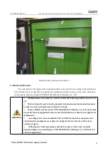
4.2.1 Brief introduction of external installation of control cabinet
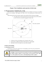
The figure above shows the main external components of GR6150 robot control cabinet, which are
as follows:
A. Electric cabinet switch (ON-OFF);
B. Panel button (the maximum button on the upper side is emergency stop button, the red button on
the left side is alarm indication, and the white button on the right side is servo power on confirmation);
C. Ethernet, remote control and USB debugging port;
D. Teaching box;
E. Teach pendant interface;
F. Fan in cabinet;
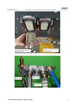
G. Coding cable, power cable, explosion-proof cable and other aviation plug-in ports;
H. The main power supply aviation plug-in port of the electric cabinet and the air inlet of the
electric cabinet;
The details are as follows:


