16
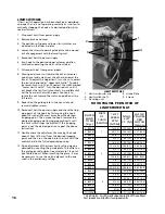
LIMIT SWITCHES
If limit switch operation has been checked as described
on page 10 and is not operating correctly or is not auto-
matically stopping the hook at a desired position, pro-
ceed as follows:
1. Disconnect hoist from power supply.
2. Remove brake end cover.
3. The positions of upper and lower limit switches are
indicated on the fiber insulator.
4. Loosen the screws to permit guide plate to be moved
out of engagement with the traveling nuts.
5. Reconnect hoist to power supply
6. Run hook to the desired upper or lower position,
cautiously operating the hoist without load.
7. Disconnect hoist from power supply.
8. Moving one travel nut toward the other increases
hook travel and away from the other decreases the
travel. To adjust the upper limit, turn the nut nearest
the switch indicated as “Upper Limit Switch”. To adjust
the lower limit, turn the nut nearest the switch marked
“Lower Limit Switch”. Turn the desired nut until it
just breaks the limit switch contacts. An audible click
will he heard as the switch opens. Continue to
rotate the nut toward the switch an additional two
full teeth.
9. Reposition the guide plate in the next slot and
securely tighten screws.
10. Reconnect hoist to power supply and check the stop-
ping point of the hook by first moving the hook
about 10 inches (254 mm) away from the desired
stopping point. Then move the hook towards the
desired stopping point by jogging cautiously until
the limit switch stops the motion. If the stopping
point is not the desired position, repeat the above
instructions.
11. Double check the adjustment by moving the hook
about 2 feet (610 mm) from the desired stopping
point and then run the hook into the limit with the
control held in the fully depressed position.
12. Fine adjustment of the screw limits setting may be
obtained by inverting the guide plate. The offset on
the plate gives adjustments equivalent to 1/2 notch
(see Table below). When inverting the plate, it may
be necessary to use the notch adjacent to the one
used in the preliminary setting.
1
4
3
2
5
LIMIT SWITCHES
1. Limit switch sub-assy
4 Guide Plate
2. Limit switch shaft
5. Screws
3. Traveling nuts
HOOK TRAVEL PER NOTCH OF
LIMIT SWITCH NUT
* At 60 Hertz. For 50 Hertz speeds are 5/6 of those listed.
Fast speeds are listed for two speed units.
RATED
LOAD
TONS
(Kg.)
*LIFT
SPEED
FPM
(MPM)
MAX.
LIFT
FT. (M)
HOOK
TRAVEL
PER
NOTCH
IN.(mm)
2 (2000)
18 (5.5)
127 (39) 1.10 (27.9)
2 (2000)
1 24 (7.3)
139 (42)
1.27 (32.3)
2 (2000)
30 (9.1)
212 (65) 0.63 (16.0)
3 (3000)
9 (2.7)
60 (18)
0.55 (14.0)
3 (3000)
12 (3.6)
65 (20)
0.64 (16.1)
3 (3000)
15.2 (4.6) 106 (32) 0.93 (23.6)
4 (4000)
9 (2.7)
60 (18) 0.55 (14.0)
4 (4000)
2 12 (3.6)
65 (20) 0.64 (16.1)
4 (4000)
15.2 (4.6)
106 (32) 0.93 (23.6)
5 (5000)
9 (2.7) 60 (18) 0.55 (14.0)
5 (5000)
12 (3.6)
65 (20)
0.64 (16.1)
5 (5000)
15.2 (4.6)
106 (32)
0.93 (23.6)
5 (5000)
6(1.8)
42 (13) 0.37 (9.3)
5 (5000)
8(2.4) 46 (14) 0.42 (10.8)
6 (6000)
6 (1.8)
42 (13)
0.37 (9.3)
6 (6000)
3 8 (2.4)
46 (14) 0.42 (10.8)
6 (6000)
10 (3.0) 71 (22) 0.63 (16.0)
7½ (7500)
6 (1.8)
42 (13) 0.37 (9.3)
7½ (7500)
10 (3.0) 71 (22)
0.63 (16.0)
PARTS
OF
CHAIN
(REEVING)
Содержание Lodestar XL
Страница 4: ...iii ...
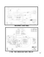
Страница 31: ...27 TWO SPEED HOIST ONLY 2 TON TWO SPEED HOIST WITH TROLLEY ...
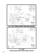
Страница 32: ...28 3 7 TON SINGLE SPEED HOIST WITH TROLLEY 3 7 TON 2 SPEED HOIST WITH SINGLE SPEED TROLLEY ...
Страница 42: ...39 40 2 TON ANTI TIPPING BRACKET KIT 670 464 ...
Страница 45: ...43 3 THRU 7 TON PLAIN GEARED AND MOTOR DRIVEN TROLLEYS EXPLODED VIEW 29 ANTI TIPPING BRACKET KIT ...
Страница 51: ...49 NOTES ...


