30
METHOD 1
1.
Disconnect the hoist from the power supply system.
2.
Remove the motor end cover (652-182). On units
with book suspension, remove the counterweight
(652-219) prior to removing the motor cover.
3.
Disengage the limit switch guide plate from the
traveling nuts (see page 15).
4.
Remove the chain container or remove the loose
end of the chain from the hoist frame.
5.
Using the procedures described on page 28 for cut-
ting load chain, cut a portion out of the last loose
end link to form a coupling link. The portion
removed should be centered on the weld and be 1/2
inch (13mm) long. Remove burrs from cut edges.
6.
Using the coupling link, attach the new chain to the
old chain. Carefully check the welds on the new
chain and make sure they are positioned the same
as the old chain. The new chain must enter the hoist
so that the welds are down and towards the lift
wheel. See illustration below. Failure to properly
position the chain will cause the chain to jam
between the liftwheel and chain guide.
7.
Re-energize power supply and carefully operate
hoist in the “down” direction until approximately 6
feet (2 M) of the new chain is hanging free on the
dead end side.
8.
ON SINGLE REEVED UNITS, remove the hook block
from the old chain, remove the coupling link, dis-
card the old chain and attach the hook block to the
new chain. ON DOUBLE REEVED UNITS, the hoist
must be removed from the trolley before reeving
the replacement load chain. For hook suspended
units, the hook must be positioned so that the dead
end bolt can be removed. If necessary, rotate hook
approximately 45 degrees following the instructions
on page 5. Now remove the chain plate and allow it
and the dead end block spacer (652-253) to slide
down the chain. Working through the cavity in
the bottom of the hoist, hold the dead end block
while loosening the dead end bolt. Remove the
dead end block and remove the dead end pin.
Remove the coupling link, pull the old chain out of
the hook block and discard the old chain. Reeve the
new load chain as described below. After reeving,
mount trolley on hoist or reposition hook, if neces-
sary, per installation instructions starting on page 4.
ON TRIPLE REEVED UNITS, remove the dead end
plate from the top of the hook block. Remove the
dead end pin and remove the old chain from the
dead end plate. Remove the coupling link, pull the
old chain out of the hook block and idler sheave
housing. Reeve the new load chain as described
below.
9. Remount the chain container or reattach the loose
end of the new chain to the hoist.
10 Reset upper and lower limit switches per page 15.
METHOD 2
1.
Completely disassemble the hoist as described on
page 26.
2.
Prior to reassembly, inspect the liftwheel, chain
guides and stripper for wear. If these parts are worn
or damaged, they could cause premature wear of
the chain. Replace worn or damaged parts.
3.
Place chain on liftwheel with welds down and
towards liftwheel as shown below. Welds must
engage the relief machined in the bottom of the
liftwheel pockets. If the chain is not properly placed
on the liftwheel, it will not be possible to install the
chain guide. After making sure the chain is correctly
installed on the liftwheel, continue to assemble the
hoist.
4.
On single reeved units, remove the hook block from
the old chain and attach it to the new chain. On
double and triple reeved units, reeve the new chain
as described below.
5.
Install the unit following the installation instructions
starting on page 4.
6.
Remount the chain container or reattach the loose
end of the new chain to the hoist frame.
7.
Reset upper and lower limit switches per page 15.
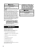
REEVING LOAD CHAIN
3, 4 AND 5 TON DOUBLE REEVED UNITS
The following instructions assume that the trolley has
been removed from the hoist or the upper hook has been
positioned to provide access to the dead end bolt and
that there is 6 feet (2 m) of chain hanging free on the
dead end side of the hoist. Based on these, reeve the load
chain as follows:
1.
Slide the suspension adapter into the hoist frame, if
has moved out of position or if it was removed.
2.
Install the dead end bolt.
3.
Attach a soft wire to the end of the chain. Feed the
wire around the hook block sheave. MAKING SURE
THERE ARE NO TWISTS, pull the chain thru the hook
block.
4.
Feed the chain thru the square opening in the chain
plate and then thru the dead end block spacer.
5.
Attach the last link of chain to dead end block using
the dead end pin.
6.
MAKING SURE THERE ARE NO TWISTS IN THE
CHAIN, slide the dead end block into the cavity in
hoist frame. Turn the dead end bolt by hand to
thread it into the dead end block. Then tighten
dead end bolt to a seating torque of 120 pound feet
(160 NM).
7.
Slide the chain plate and spacer up the chain and
attach the chain plate to the hoist frame.
8.
Retrace the chain and make sure there are no twists.
If there are twists, start over.
INSTALL LOAD
CHAIN PROPERLY
ON LIFTWHEEL
WARNING
Improper installation (reeving) of load chain can
result in dropped load.
TO AVOID INJURY:
Properly reeve load chain per the following instructions.
!
Содержание Lodestar XL
Страница 4: ...iii ...
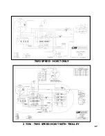
Страница 31: ...27 TWO SPEED HOIST ONLY 2 TON TWO SPEED HOIST WITH TROLLEY ...
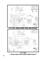
Страница 32: ...28 3 7 TON SINGLE SPEED HOIST WITH TROLLEY 3 7 TON 2 SPEED HOIST WITH SINGLE SPEED TROLLEY ...
Страница 42: ...39 40 2 TON ANTI TIPPING BRACKET KIT 670 464 ...
Страница 45: ...43 3 THRU 7 TON PLAIN GEARED AND MOTOR DRIVEN TROLLEYS EXPLODED VIEW 29 ANTI TIPPING BRACKET KIT ...
Страница 51: ...49 NOTES ...

