background image

45

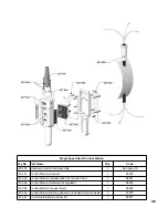
Single Speed Hoist Control Station

Key No.

Part Name

Qty.

Code

627-250

Standard Control Cord Assembly

1

See page 35

627-551

Control Station Grommet

1

58278

627-552

Control Station (Includes 627-551 thru 627-567)

1

58272

627-563

Control Station Hardware Kit w/gasket

1

58275

627-565

Control Station 1-speed Insert

1

58255

627-566

Control Station Warning Label Kit (Includes Exterior Labels)

1

57276

627-567

Contol Station Button Label Kit

1

58277

Содержание Lodestar XL

Страница 1: ...ies 2 through 7 tons 2000 through 7500 kg Follow all instructions and warnings for inspecting maintaining and operating this hoist The use of any hoist presents some risk of personal injury or property damage That risk is greatly increased if proper instructions and warnings are not followed Before using this hoist each operator should become thoroughly familiar with all warnings instructions and ...

Страница 2: ...arts and repair requirements promptly and efficiently Below is a list of the Master Parts Depots in the United States and Canada To quickly obtain the name of the U S Service Center located nearest you call 314 869 7200 FAX 314 869 7226 In the following list the Canadian Service Centers are indicated i UNITED STATES MASTER PARTS DEPOT CANADIAN SERVICE CENTERS MISSOURI Distributed by Tri State Equi...

Страница 3: ...ged or worn load chain 6 Not use the hoist to lift support or transport people 7 Not lift loads over people 8 Not operate a hoist unless all persons are and remain clear of the supported load 9 Not operate unless load is centered under hoist 10 Not attempt to lengthen the load chain or repair dam aged load chain 11 Protect the hoist s load chain from weld splatter or other damaging contaminants 12...

Страница 4: ...iii ...

Страница 5: ... TROLLEY 23 ELECTRICAL DATA 24 25 WIRING DIAGRAMS 26 28 DISASSEMBLY 29 REASSEMBLY 29 REMOVALANDREPLACEMENTOFLOADCHAIN29 REEVING LOAD CHAIN 3 4 AND 5 TON DOUBLE REEVED UNITS 30 5 6 AND 71 2 TON TRIPLE REEVED UNITS 31 CUTTING CHAINS 31 TESTING 32 REPAIR PARTS ORDERING INSTRUCTIONS 32 EXPLODED VIEWS AND PARTS LISTS 33 48 FOREWORD This manual contains important information to help you properly install...

Страница 6: ...FPM 6 18 8 24 3 9 4 12 2 6 2 7 8 2 6 2 7 8 2 6 TWO SPEEDS N A N A N A N A MPM 1 8 5 5 2 4 7 3 9 2 7 1 2 3 6 6 1 8 8 2 4 6 1 8 8 2 4 6 1 8 FEET 127 139 71 60 65 106 42 46 42 46 71 42 71 MAXIMUM LIFT METERS 39 42 22 19 21 32 13 14 13 14 22 13 22 REEVING OF LOAD CHAIN SINGLE DOUBLE TRIPLE MINIMUM HEADROOM HOOK SUSPENDED IN mm 25 635 35 31 897 36 18 919 N A TROLLEY SUSPENDED IN mm 28 69 729 33 841 33 ...

Страница 7: ...ingle load bar or for sus pending the hoist from a fixed structure 3 LUG SUSPENSIONS Lug suspensions are required to suspend the LODESTAR XL Electric Hoist from plain geared or motor driven trolleys described below When the hoist is to be suspended from a plain geared or motor driven trolley the lug suspension is attached to the hoist prior to shipment LUG SUSPENSION PLAIN TROLLEYS These are manua...

Страница 8: ...ension trolley and chain container for damage that may have occurred during shipment If there is damage refer to the packing slip envelope Make sure that the power supply to which the hoist is to be connected is the same as that shown on the iden tification plate located on the bottom of the hoist For single speed dual voltage hoists refer to instructions on page 8 INSTALLING SUSPENSION A HOOK SUS...

Страница 9: ...sely reassemble keeper plate to suspension adapter so that the hook is free to swivel approximately 45 degrees in either direction The hook will be made rigid after suspension is attached to the hoist Attach the XL label from the kit to counterweight in the recess provided for same 2 2 Ton Single Reeved Units As shipped from the facto ry the hook is rigid with the plane of the hook parallel to the...

Страница 10: ...ler sheave hanger 5 6 and 7 1 2 ton triple reeved units Then tighten the dead end bolt to a seating torque of 120 pound feet 160 NM INSTALLING LUG SUSPENSION 3 4 5 6 AND 7 1 2 TON MOUNTING TROLLEY ON HOIST The following instructions are provided to cover mount ing plain geared and motor driven trolleys after the hoist has been reassembled following inspection and or repair On units shipped from fa...

Страница 11: ...es and not exert impact force on the hoist Trolleys are mounted on the hoist prior to shipment and side frames are positioned for the nominal beam flange specified on the order However due to variations in beam flange widths actual beam flange width should be measured to determine the exact distribution of the spacer washers See Mounting Trolley On Hoist Section WARNING Operating the trolley on a ...

Страница 12: ...ge Lift hoist trolley assembly up so that trackwheels are riding on beam flange Draw side frames together by tightening the sus pension bolt nuts snugly Be sure to install cotter pins through slotted nuts and hole in suspension bolts and spread legs of cotter pins to secure on 2 ton units For 3 7 1 2 ton units be sure lock washers are positioned properly on the suspension pins and completely tight...

Страница 13: ...ed to power cord to indicate that the hoist has been converted to operate on 230 or 220 volts and restamp hoist identification plate accordingly If the hoist is suspended from a single speed motor driven trol ley it will also be necessary to change the trolley motor connections To do this remove the cover from the ter minal box mounted on the side of the trolley motor and reconnect the trolley mot...

Страница 14: ...the chain and allow the load to drop TO AVOID INJURY Do not allow the hook block to contact the bottom of the hoist or the loose end chain to become taut NOMINAL MINIMUM MIN VOLTAGE POWER OPERATING AT INSTANT SUPPLY VOLTAGE OF START 208 3 60 187 172 220 3 50 198 182 230 3 60 207 190 380 3 50 365 336 415 3 50 399 367 460 3 60 414 380 The drop in voltage upon energizing the hoist should not be below...

Страница 15: ...perate in the SLOW speed position as the hoist will pick up a capacity load at FAST speed from a standing start In other words it is not nec essary to hesitate at the slow position when moving control from STOP and FAST position or vice versa 4 If material being handled must be immersed in water pickling baths any liquid dusty or loose solids use a sling chain of ample length so that the hook is a...

Страница 16: ...gainst the hook latch and or hook tip Apply load to hook bowl or saddle MAINTENANCE The type of service to which the hoist is subjected can be classified as Normal Heavy or Severe Normal Service Involves operation with randomly distrib uted loads within rated load limit or uniform loads less than 65 percent of rated load for not more than 25 per cent of the time Heavy Service Involves operating th...

Страница 17: ...use the link adjacent to the loose end link for this purpose Compare these two measurements If the stock diameter of the worn link is 0 010 inches 0 254mm or greater less than the stock diameter of the unworn link the chain must be replaced Note that worn chain can be an indication of worn hoist components For this reason the hoist s chain guides hook blocks and liftwheel should be examined for we...

Страница 18: ...e wear of brake parts and brake adjustment see page 15 g External evidence of pitting or any deterioration of contactor contacts Check the operation of the control station making sure the buttons operate freely and do not stick in either position h Inspect the electrical cords and cables and control station enclosure for damaged insulation i Inspect trolley trackwheels for external wear on tread a...

Страница 19: ...rcinogenic materials TO AVOID HEALTH PROBLEMS Never use used motor oils as a chain lubricant Only use Lubriplate Bar and Chain Oil 10 R as a lubricant for the load chain Bearings All bearings except the lower hook thrust bearings are pre lubricated or are in an oil bath and need no lubrication The lower hook thrust bearing should be lubricated at least once a month with heavy duty machine oil Misc...

Страница 20: ...pping point by jogging cautiously until the limit switch stops the motion If the stopping point is not the desired position repeat the above instructions 11 Double check the adjustment by moving the hook about 2 feet 610 mm from the desired stopping point and then run the hook into the limit with the control held in the fully depressed position 12 Fine adjustment of the screw limits setting may be...

Страница 21: ...h it is to be installed and the voltage on which the trolley operates ADJUSTMENT The motor brake should be checked periodically for wear of the friction discs and or proper adjustment of the solenoid air gap Refer to Figure 1 Normal lining wear will cause the solenoid lever 8 to move away from the solenoid frame 79 and thus increase the air gap and trolley stopping time When the air gap reaches ap...

Страница 22: ...on of the various components using the recommended lubricants see page 15 Replacement of Coil Refer to Figure 1 on page 17 and Exploded View Drawing on page 48 1 De energize the power supply to the trolley and remove the motor brake assembly from the gear reducer 2 Remove housing 3 from the brake and disconnect the coil wires from the cord 3 Insert screw driver between support plate 126 Fig 1 and ...

Страница 23: ...for electrical continuity and repair or replace defective part C Press the other control and the hook should respond Adjust limit switches as described on page 15 D Check electrical continuity thru thermal switch If it is open allow motor to cool Should this not correct the trouble check electrical continuity of other parts and repair or replace defective part E Use the voltage and frequency indic...

Страница 24: ...e in circuit control sta tion contacts not making lower limit switch contacts open A Phase failure A Brake slipping B Excessive load C Protector slipping A Excessive load B Low voltage C Phase failure or unbalanced cur rent in phases D Brake dragging A Check connections with the wiring diagram B Refer to installation instructions on page 9 all hoists A See Item 1H B See Item 1D Also check opera ti...

Страница 25: ...mbient temperature of 104 F 40 C the frequency of hoist operation must be lim ited to avoid overheating of motor Special provisions should be made to ventilate the space of shield the hoist from radiation D Avoid excessive inching jogging or plugging This type of oper ation drastically shortens the motor and contactor life and causes excessive brake wear E See Item 1B F Check brake adjustment as d...

Страница 26: ...hase reversal B Brake not releasing A Phase reversal A Open or shorted motor wind ing loose or broken wire in circuit speed selecting contac tor stuck in opposite speed mode Replace motor repair wire and or replace speed selecting contactor B See Item 1B A See Item 11A B Open or shorted winding in speed selecting contactor coil Loose connection or broken wire in circuit Mechanical binding in conta...

Страница 27: ...t A Excessive load B Low voltage C Unbalanced current in the phases D Brake dragging A Open circuit grounded or faulty connection in hoist wiring B See Item 1B C See Item 1D D See Item 1F E See Item 1E A See Item 1D A See Item 1H B See Item 1F C See Item 1B D Check electrical continuity and connections Check that the cor rect coil has been installed The coil for dual voltage units oper ate on 230 ...

Страница 28: ...ition COILS HOIST REVERSING CONTACTOR COILS HOIST SPEED SELECTING CONTACTOR COILS TROLLEY REVERSING CONTACTOR COILS HOIST BRAKE COILS TROLLEY BRAKE COILS TROLLEY SPEED SELECTOR VOLTAGE 115 48 24 115 48 24 115 48 24 220 240 380 480 575 220 240 380 480 575 220 240 380 480 2 Ton 575 115 48 24 CURRENT DRAW AMPS AT 60 HERTZ 0 09 0 46 0 49 0 11 0 25 N A 0 17 0 30 1 00 1 39 0 86 0 39 0 27 0 16 0 09 0 20 ...

Страница 29: ...T8 T1 T2 T11 T12 3 PHASE KW SYN CURRENT AMPS T2 T5 T7 T9 T1 T3 T11 T13 AT 60 HERTZ AT 60 HERTZ T3 T6 T8 T9 T2 T3 T12 T13 208 240 380 480 5 38 1200 1 95 98 15 9 31 2 208 240 380 480 5 38 600 3 75 1 88 14 28 550 575 5 38 1200 0 70 101 2 550 575 5 38 600 1 80 86 3 208 240 25 50 19 38 600 1200 3 00 2 60 25 0 27 1 380 480 25 50 19 38 600 1200 1 30 1 10 105 9 106 9 208 240 25 50 19 38 900 1800 4 5 8 1 1...

Страница 30: ...TYPICAL WIRING DIAGRAMS Wiring diagrams shown are representative Consult wiring diagram in hoist or furnished with unit 26 SINGLE SPEED HOIST ONLY 2 TON SINGLE SPEED HOIST WITH TROLLEY ...

Страница 31: ...27 TWO SPEED HOIST ONLY 2 TON TWO SPEED HOIST WITH TROLLEY ...

Страница 32: ...28 3 7 TON SINGLE SPEED HOIST WITH TROLLEY 3 7 TON 2 SPEED HOIST WITH SINGLE SPEED TROLLEY ...

Страница 33: ...eel gear 652 105 from the lift wheel 652 111 13 Remove the motor housing 652 107 from the main housing 652 110 14 Remove the chain stripper 652 114 and chain guide 652 113 15 On the 3 4 and 5 ton Double Reeved units remove the dead end block 652 204 and chain 16 Remove the liftwheel 652 111 from the main housing Slots are provided in intermediate plate 652 109 to aid in the removal of screws REASS...

Страница 34: ...ain as described below 9 Remount the chain container or reattach the loose end of the new chain to the hoist 10 Reset upper and lower limit switches per page 15 METHOD 2 1 Completely disassemble the hoist as described on page 26 2 Prior to reassembly inspect the liftwheel chain guides and stripper for wear If these parts are worn or damaged they could cause premature wear of the chain Replace worn...

Страница 35: ... SURE THERE ARE NO TWISTS IN THE CHAIN insert the last link of the chain into the slot in the dead end plate Secure the chain using the dead end pin and attach the dead end plate to top of hook block Tighten the dead end plate screws to a seating torque of 120 pound feet 160 NM 4 Retrace chain and make sure there are no twists If there are twists start over CUTTING CHAINS Hoistaloy load chain is h...

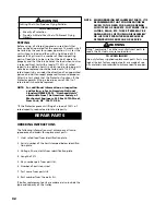
Страница 36: ...rated capacity reduce load to rated capacity ORDERING INSTRUCTIONS The following information must accompany all corre spondence and orders for replacement parts 1 Hoist rated load from identification plate 2 Serial number of the hoist stamped below identifica tion plate 3 Voltage Phase Hertz from identification plate 4 Length of lift 5 Key number part from parts list 6 Number of parts required 7 P...

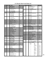
Страница 37: ...0416 652 134 1 LIMIT SWITCH INPUT SHAFT SEAL 80417 652 135 1 TRANSFORMER 208 240 380 480 VOLT 68810 PRIMARY 115 VOLT SECONDARY 208 240 380 480 VOLT 70793 CON T PRIMARY 48 VOLT SECONDARY KEY NO NO REQ D PART NAME PART NUMBER 652 135 1 208 240 380 480 VOLT 68811 PRIMARY 24 VOLT SECONDARY 550 575 VOLT PRIMARY 68786 115 VOLT SECONDARY 652 136 1 HOIST REVERSING CONTACTOR WITH 115 VOLT COILS 52749 48 VO...

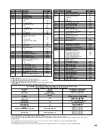
Страница 38: ...652 178 1 CHAIN PLATE 2 TON 52046C 3 AND 4 TON 52048C 652 179 HOOK BLOCK SCREW 2 TON 4 REQ D 982369 3 AND 4 TON 4 REQ D 80423 5 6 AND 7 1 2 TON 2 REQ D 80423 652 180 2 CHAIN PLATE OR IDLER HOUSING SCREW 987288 KEY NO NO REQ D PART NAME PART NUMBER 652 181 1 BRAKE END COVER 52028C 652 182 1 MOTOR END COVER 52031C 652 183 1 IDENTIFICATION PLATE LODESTAR XL 70728 652 184 4 BRAKE END COVER SCREW 80409...

Страница 39: ...IFT 28450 TWO SPEED HOIST WITH 10 FT LIFT 36584 SINGLE OR TWO SPEED HOIST WITH 51711 10 FT LIFT AND MOTOR DRIVEN TROLLEY FOR OTHER LIFTS CONTACT CM 652 251 2 END COVER GASKET WEATHER PROOF UNITS ONLY 52759 652 252 2 CONTACTOR MOUNTING SCREW 982686 652 253 1 DEAD END BLOCK SPACER 52064 652 254 1 CONV T B LABEL LONG 52721 652 255 1 TROLLEY CORD HOLE PLUG 989052 652 256 1 LOOSE END SCREW 982667 652 2...

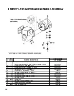
Страница 40: ...POWER CONNECTOR LOCKNUT 989771 5 4 LOCKWASHER BET 3006 6 4 HEX HEAD BOLT 3 8 16 X 7 8 BET 3007 7 1 POWER CORD 51120 8 WIRE NUT 983812 9 1 POWER CORD CONNECTOR 89926 10 1 WEATHERPROOF 0 RING 983967 11 LINE CONNECTOR 982158 SPECIFY QTY SPECIFY QTY REF NO NO REQ D PART DESCRIPTION PART NUMBER 3 7 1 2 TON 3 THRU 7 TON MOTOR AND GEAR BOX ASSEMBLY TROLLEY BRAKE OPTIONAL SEE PAGE 47 FOR TROLLEY BRAKE ASS...

Страница 41: ...37 For control station and control sta tion parts see pages 45 and 46 38 SEE ALSO 652 219 COUNTER WEIGHT IF ORDERING HOOK SUS PENSION PARTS SEPARATELY ...

Страница 42: ...39 40 2 TON ANTI TIPPING BRACKET KIT 670 464 ...

Страница 43: ...FPMTROLLEY 30 4MPM 58407 35 65FPMTROLLEYS 10 7 19 8MPM 58453 25 50FPMTROLLEYS 7 6 15 2MPM 58453 Con t 50 100FPMTROLLEY 15 2 30 4MPM 58453 2 TON Plain Geared and Motor Driven Trolleys Parts List Part Number Key No No Req d Part Name 2 TON 652 186 2 WARNINGLABEL ELECTRICAL 24842 652 300 1 TROLLEYPOWERCORD 51117 652 301 1 HOISTSUSPENSIONADAPTER 52059 652 302 1 SUSPENSIONADAPTERSCREW DEADENDBOLT 98720...

Страница 44: ...REQ D PART NAME PART NUMBER 2 TON 670 347 1 MOTORPINIONFOR 35AND65FPMTROLLEYS 10 7and19 8MPM 54356 50FPMTROLLEYS 15 2MPM 58406 100FPMTROLLEYS 30 4MPM 58406 35 65FPMTROLLEYS 10 7 19 8MPM 54356 25 50FPMTROLLEYS 7 6 15 2MPM 54356 50 100FPMTROLLEYS 15 2 30 4MPM 54356 670 348 1 MOTORPINIONPIN 988263 670 349 1 DRIVENGEARKEY 989096 670 350 2 PINIONBEARINGSPACER 58456 670 351 1 INTERMEDIATEBEARINGSPACER 5...

Страница 45: ...43 3 THRU 7 TON PLAIN GEARED AND MOTOR DRIVEN TROLLEYS EXPLODED VIEW 29 ANTI TIPPING BRACKET KIT ...

Страница 46: ...1529 700T 1831 BET 3833 14 40 SPACER WASHERS 700T 1416 700T 1714 BET 2817 700T 1532 700T 1834 BET 3836 15 2 SUSPENSION PIN FOR 4 TO 6 1 4 FLG AND PATENTED TRACK 700T 1418 700T 1715 BET 2818 700T 1535 700T 1837 BET 3839 6 3 8 TO 8 5 8 FLG 700T 1420 700T 1716 BET 2819 700T 1537 700T 1839 BET 3841 8 3 4 TO 11 FLG 700T 1422 700T 1717 BET 2820 700T 1539 700T 1841 BET 3843 16 2 BUSHING 700T 1723 700T 18...

Страница 47: ... 551 Control Station Grommet 1 58278 627 552 Control Station Includes 627 551 thru 627 567 1 58272 627 563 Control Station Hardware Kit w gasket 1 58275 627 565 Control Station 1 speed Insert 1 58255 627 566 Control Station Warning Label Kit Includes Exterior Labels 1 57276 627 567 Contol Station Button Label Kit 1 58277 ...

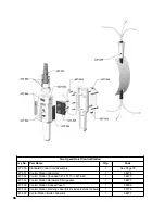
Страница 48: ...51 Control Station Grommet 1 58278 627 552 Control Station Included 627 551 Thru 627 567 1 58273 627 563 Control Station Hardware Kit w gasket 1 58275 627 565 Control Station 2 speed Insert 1 58256 627 566 Control Station Warning Label Kit Includes Exterior Labels 1 57276 627 567 Contol Station Button Label Kit 1 58277 ...

Страница 49: ... 635 156 Control Station Includes 627 551 Thru 627 567 1 58220 CM 627 553 Control Station Housing Kit Includes Housing Boots Collar Gasket Hardware 1 58288 627 563 Control Station Hardware Kit w gasket 1 58279 627 565 Control Station 1 Speed Insert 1 58522 Control Station 2 Speed Insert 1 58256 627 566 Control Station Warning Label Kit 1 57276 627 567 Contol Station Button Label Kit 1 58277 ...

Страница 50: ...g External Lead Hole 16 1 Bearing 17 1 Solenoid Lever 18 1 Retaining Ring 19 2 Spacer 20 2 Torque Adjusting Screw 21 2 Wear Adjusting Screw 22 2 Pressure Spring 23 1 Lever Arm And Stop Nut Assembly 24 1 Bearing Pin 25 1 Support Plate And Stop Nut Assembly 26 1 Pivot Pin 27 1 Solenoid Kit Includes Plunger Link Frame Link Screw Link Nut And Mounting Screws 28 1 Coil Kit Includes Coil Plunger Guides ...

Страница 51: ...49 NOTES ...
Страница 52: ...T Seller shall not be liable for any damage injury or loss arising out of the use of the goods if prior to such damage injury or loss such goods are 1 damaged or misused following Seller s delivery to carrier 2 not maintained inspected or used in compliance with applicable law and Seller s written instruc tions and recommendations or 3 installed repaired altered or modified without compliance with...

Отзывы: