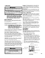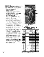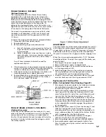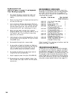
29
DISASSEMBLY
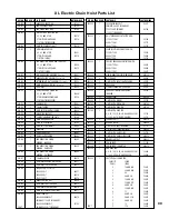
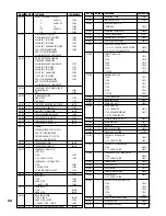
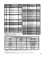
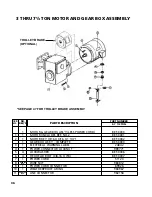
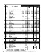
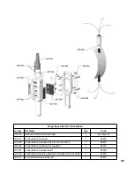
Refer to pages 30 through 40 for exploded view and
parts list. The following are general guide lines for dis-
assembling the XL Hoist. Prior to disassembly:
1. Operate the hoist in the “down” direction until the
lower limit is reached. Remove the brake end cover
(652-181) and disengage the limit switch guide plate
from the traveling nuts (see page 15). Remove the
chain container or remove the loose end screw (652-
256) and washers (652-257 and 652-258).
2. Carefully run the chain out of the hoist. On 3 and 4
ton units, the chain will remain suspended from the
dead end block (652-204).
3. Disconnect the hoist from the power supply system
and Lockout/Tagout disconnecting means.
4. Drain the oil from the hoist.
5. Remove the hoist from its support (hook suspended
units) or remove the hoist and trolley from the beam.
Remove the trolley from the hoist.
These guide lines cover the disassembly of the major
mechanical components; not covered is the removal of
obvious items such as hardware and seals. While disas-
sembling the hoist, care should be taken so as to not
damage the seals. Seals should be inspected for nicks or
damage that could cause oil leaks. Damaged seals
should be replaced prior to reassembly.
1. Remove brake end cover (652-181).
2. Remove the brake assembly (652-161) and brake hub
(652-142).
3. Remove the entire limit switch assembly and the limit
switch worm (652-146).
4. Remove the motor end cover (652-182) and the com-
plete motor (652-162). Coupling (652-103) should
remain on motor shaft.
5. On the 2, 3 and 4 ton units, remove chain plate
(652-178). On the 5 and 6 ton units,remove the idler
wheel housing (652-211) with idler wheel and bear-
ings.
6. *Remove the brake housing (652-108) and gasket (652-118).
7. Remove the drive shaft and pinion (652-112).
8. Remove the Protector (652-160).
9. *Remove the intermediate plate (652-109) from the
main housing (652-110) and remove gasket (652-
118).
10. Remove the limit switch gear (652-149) from the
limit switch input shaft (652-104) and remove the
shaft from the intermediate plate.
1
1. Remove the second gear (652-159) from third reduc-
tion pinion and shaft (652-106) and remove the third
reduction pinion and shaft from the main housing
(652-110).
12. Remove the liftwheel gear (652-105) from the lift
wheel (652-111).
13. Remove the motor housing (652-107) from the main
housing (652-110).
14. Remove the chain stripper (652-114) and chain
guide (652-113).
15. On the 3, 4, and 5 ton (Double Reeved) units,
remove the dead end block (652-204) and chain.
16. Remove the liftwheel (652-111) from the main housing.
*Slots are provided in intermediate plate (652-109) to
aid in the removal of screws.
REASSEMBLY
The reassembly of the hoist is, basically, the reverse of
the above disassembly sequence. However, during
reassembly:
1. If new seals are installed, make sure the lip of the
seal is on the oil side.
2. Apply a light coat of gear oil to lips of all seals and
surfaces of shafts that pass thru the seals.
3.
Carefully slide the shafts through the seals.
4.
The frame screws used to attach the motor and gear
housings to the main frame should be tightened to
a seating torque of 21 pound feet (28 NM).
5. Lubricate, especially the splines, as specified on page 14.
6. Make sure that “this side out” embossed on the lift-
wheel gear is visible when the gear is assembled to
the liftwheel.
7. Place the load chain (with welds down and towards
liftwheel. See illustration on page 27) over the lift-
wheel before attaching the motor housing to the
main frame. After assembly reeve chain per page 27.
8.
Follow instructions starting on page 4 when re-
installing the unit.
9. After installation, test the unit as indicated on page 29.
REMOVAL AND REPLACEMENT OF LOAD CHAIN
Hoist load chain can be removed and installed using one
of the following methods. Method 1 is recommended if
only the load chain is replaced. Method 2 is recommended
when the entire hoist is disassembled for repair and /or
inspection.
WARNING
Working in or near exposed energized electrical
equipment presents the danger of electrical shock.
TO AVOID INJURY:
DISCONNECT POWER AND LOCKOUT/TAGOUT DIS-
CONNECTING MEANS BEFORE REMOVING COVER
OR SERVICING THIS HOIST.
USE ONLY STAR (H) GRADE LOAD CHAIN AND
FACTORY REPLACEMENT PARTS. USE OF OTHER
CHAIN AND PARTS MAY BE DANGEROUS AND
VOIDS FACTORY WARRANTY.
!
WARNING
USE OF COMMERCIAL OR OTHER MANUFACTURERS’
CHAIN AND PARTS TO REPAIR XL HOISTS MAY
CAUSE LOAD LOSS.
TO AVOID INJURY:
Use only factory supplied replacement load chain
and parts. Chain and parts may look alike, but
factory chain and parts are made of specific mate-
rial or processed to achieve specific properties.
Star and 2-digit
year code
Содержание Lodestar XL
Страница 4: ...iii ...
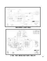
Страница 31: ...27 TWO SPEED HOIST ONLY 2 TON TWO SPEED HOIST WITH TROLLEY ...
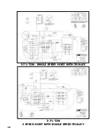
Страница 32: ...28 3 7 TON SINGLE SPEED HOIST WITH TROLLEY 3 7 TON 2 SPEED HOIST WITH SINGLE SPEED TROLLEY ...
Страница 42: ...39 40 2 TON ANTI TIPPING BRACKET KIT 670 464 ...
Страница 45: ...43 3 THRU 7 TON PLAIN GEARED AND MOTOR DRIVEN TROLLEYS EXPLODED VIEW 29 ANTI TIPPING BRACKET KIT ...
Страница 51: ...49 NOTES ...

