9
P/N: 192065084 Rev AA March 2020
(ENGLISH)
ENGLISH
MAINTENANCE (CONTINUED)
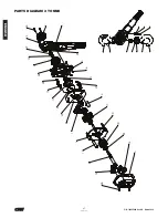
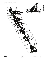
DISASSEMBLY AND ASSEMBLY
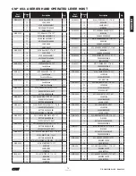
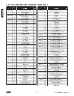
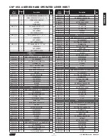
The parts illustration and list in the repair parts section show the
general arrangement and name of the parts of the CM
®
653-A
SERIES lever hoist. These should be used when disassembling and
re-assembling the units so that all parts are properly installed.
DISASSEMBLY
To replace the liftwheel or stripper, completely disassemble the unit:
remove the chain (See REPLACING LOAD CHAIN, page 11) and then
remove the following: T2 Cylinder Screws M5x30, Handwheel, Lever
Handle Assembly (Button Head Screw and 2 Lock Nuts) Center Lock
Nut, Washer, Bushing, Ratchet Wheel (or Overload Assembly), Brake
Side Cover (4 Lock Nuts) Pressunre Spring, Ratchet Disc Assembly,
Disc Hub, Lever Side Plate Assembly, Chain Guide, Stripper.
On the gear side, remove the following: 4 Lock Nuts, Gear Case
Assembly, Spur Gear Assembly, Drive Shaft, Drive Shaft Washer,
Load Gear, Top Hook Shaft, Upper Hook Assembly, Gear Side Plate
Assembly
ASSEMBLY
Prior to re-assembly, check all parts for excessive wear, cracks and
distortion. Replace parts as necessary and then re-assemble the unit
in reverse to the order given above
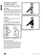
GEAR TIMING
When assembling gears, they must be orientated with the timing
marks orientated as shown. (use figure “Gear Timing”) Note: For 1t
+ 1.5t Tonne units, orientation of pinion/gear assemblies A and B are
not relevant providing the timing marks are orientated as shown and
one of each (A & B) assembly is present.
Figure 10 - Gear Timing
(0.75t + 1t + 1.5t)
Figure 11 - Gear Timing
(2t + 3t + 6t)
Timing Marks
Timing Marks
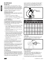
REPLACING LOAD CHAIN
To replace the load chain, remove the lower hook block and chain
stop from the chain. Move the directional lever to the neutral “N” and
pull the old chain out of the hoist. Feed a length of soft wire through
one side of the chain guide and over the liftwheel until it comes out
on the other side of the chain guide. Attach the wire to the end of the
new chain. Position the chain so that the first link to enter the chain
guide will be an upstanding link and the welds on all upstanding
links will be away from the liftwheel. Pull on the wire until the chain
engages the liftwheel. Turn the handwheel while pulling on the wire,
until the chain comes out of the chain guide. Pull the chain through
and remove the wire. Attach the lower hook block to the chain that is
directly below the upper hook.
Chain Installation Single Reeved (0.75 – 3 Tonne)
Chain installation Double Reeved (6 Tonne)
Columbus McKinnon
Industrial Products GmbH
Yale-Allee 30
42329 Wuppertal / Germany
D
E
F
C
1
2
3
B
A
3
2
1
5
C
D
4
6
7
8
A
B
NOTICE TO PERSONS RECEIVING THIS DRAWING AND/OR TECHNICAL INFOR
MATION
Columbus McKinnon Industrial Products GmbH claims proprietary r
ights in the material disclosed hereon. This drawing and/or tec
hnical information is issued in confidence
for engineering information only and may not be reproduced or u
sed to manufacture anything shown or referred to hereon without
direct permission
from Yale to the user. This drawing and/or technical informatio
n is loaned for mutual assistance and is subject to recall by Y
ale at any time.
This drawing and/or technical information is the property of Ya
le.
Columbus McKinnon
Industrial Products GmbH
Wuppertal / Germany
By
Date
Description of change
Rev.
ECN
Edges According to
DIN 6784
Specified Tolerances
ISO 8015
Material No:
Standard:
05/09/2019 KON7
192051824-K
Kettenverlauf
Chain installation
CM 653-A - 6t
KON7
KON7
Velbert
05/09/2019
05/09/2019
A3
Format
1
1
Sheet
Number:
Description:
mm
Dimensional Units
General Tolerances
ISO 2768-mk
Material:
1:3
Original scale:
Original project:
Design Authority:
Approved:
Drawn:
Modeled:
First Angle Projection
Содержание 5310A
Страница 71: ...NOTES 25 P N 192065084 Rev AA March 2020...
Страница 72: ...NOTES 26 P N 192065084 Rev AA March 2020...
Страница 73: ...NOTES 27 P N 192065084 Rev AA March 2020...
Страница 74: ...P N 192065084 Rev AA March 2020...


