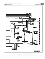
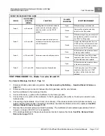

TROUBLESHOOTING AND ELECTRICAL SYSTEM:
GASOLINE VEHICLES
Test Procedures
11
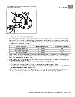
8.
Connect the black (–) probe of the multimeter to the 18-gauge purple wire (w47) at the key switch multi-pin
connector.
9.
Connect the red (+) probe of the multimeter to the female side of the carburetor solenoid bullet connector.
10. The reading should indicate an over limit (no continuity). If the diode conducts current (shows continuity) with
the meter probes connected as described, the diode has failed and must be replaced.
11. Reverse the multimeter probes and note the reading. The multimeter should indicate approximately 540 mV,
however, a range of 400-700 mV is acceptable.
12. If the readings obtained in the previous steps are incorrect, replace the diode.
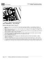
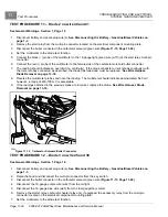
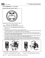
TEST PROCEDURE 13 – Diode 4 on wire 130 and 122
See General Warnings, Section 1, Page 1-2.
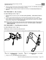
1.
Disconnect battery and spark plug wire(s).
See Disconnecting the Battery – Gasoline/Diesel Vehicles on
2.
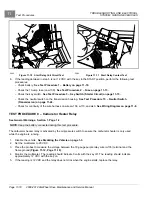
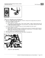
Raise the hood and disconnect the multi-pin connector from the key switch.
3.
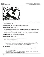
Disconnect the bullet connector in the carburetor solenoid green wire
.
4.
Set the multimeter to the diode test function.
5.
Connect the black (–) probe of the multimeter to the frame (ground).
6.
Connect the red (+) probe of the multimeter to the female side of the carburetor solenoid bullet connector.
7.
The reading should indicate an over limit (no continuity). If the diode conducts current (shows continuity) with
the meter probes connected as described, the diode has failed and must be replaced.
8.
Reverse the multimeter probes and note the reading. The multimeter should indicate approximately 540 mV,
however, a range of 400-700 mV is acceptable.
9.
If the readings obtained in the previous steps are incorrect, replace the diode.
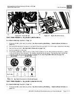
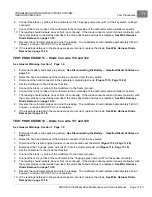
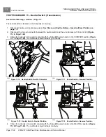
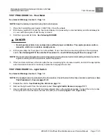
TEST PROCEDURE 14 – Diode 5 on wire 131 and 129
See General Warnings, Section 1, Page 1-2.
1.
Disconnect battery and spark plug wire(s).
See Disconnecting the Battery – Gasoline/Diesel Vehicles on
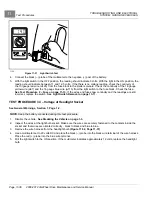
2.
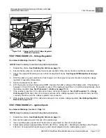
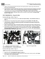
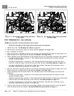
Raise the hood and disconnect the multi-pin connector from the key switch.
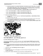
3.
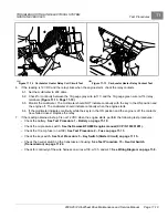
Disconnect the six wire engine harness connector located near the starter
.
4.
Disconnect the 16-gauge green wire (w127) from the starter solenoid coil
.
5.
Set the multimeter to the diode test function.
6.
Connect the black (–) probe of the multimeter to the frame (ground).
7.
Connect the red (+) probe of the multimeter to the 16-gauge green wire (w127) at the spade connector.
8.
The reading should indicate an over limit (no continuity). If the diode conducts current (shows continuity) with
the meter probes connected as described, the diode has failed and must be replaced.
9.
Reverse the multimeter probes and note the reading. The multimeter should indicate approximately 540 mV,
however, a range of 400-700 mV is acceptable.
10. If the readings obtained in the previous steps are incorrect, replace the diode.
2008-2012 All-Wheel Drive Maintenance and Service Manual
Page 11-23
Содержание Carryall 295 SE
Страница 2: ......
Страница 20: ......
Страница 28: ......
Страница 58: ......
Страница 66: ......
Страница 100: ......
Страница 122: ......
Страница 150: ......
Страница 157: ......
Страница 190: ......
Страница 197: ......
Страница 236: ......
Страница 284: ......
Страница 386: ......
Страница 394: ......
Страница 442: ......
Страница 452: ......
Страница 454: ......
Страница 455: ......
Страница 456: ......


