background image

20 


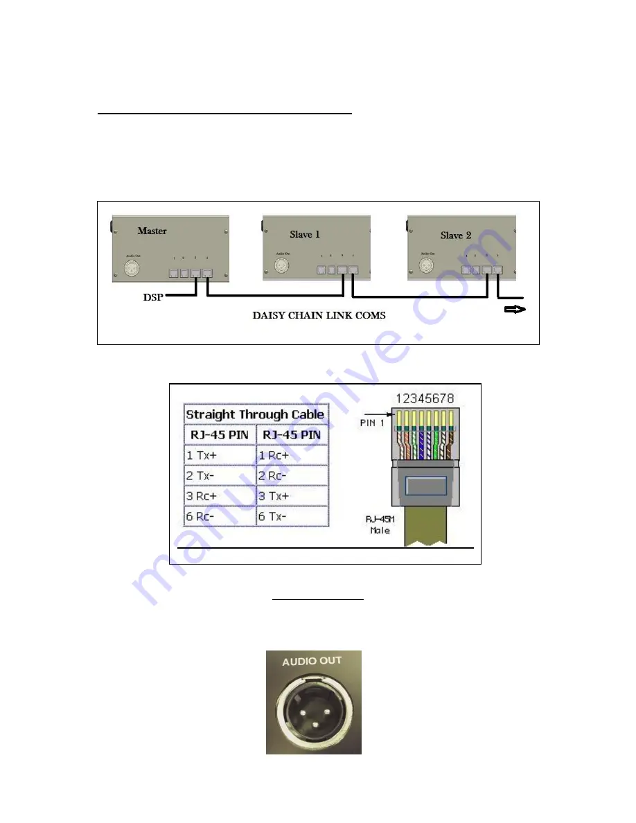
Slave wiring communication link connections 


When adding slave units to the master, connect RJ45 (straight in line connections) 
from socket 4 on the master to socket 3 on the 1

st

 slave then connect socket 4 on the 

1

st

 slave to socket 3 on the next slave in line etc etc.... 


Audio Out Socket 

An XLR audio output socket is provided for connection to a mixer or DSP. Phantom 
power adaptor is inbuilt and requires an external 9-48VDC phantom power to be 
applied. 


Содержание CCRM 4000-Retracta

Страница 1: ...CCRM 4000 Retracta Motorized Ceiling Microphone Installation Manual and user Guide ...

Страница 2: ...arnings in this manual they are there for the safety of you and others Keep these instructions in a safe place in case they need to be referred to later Do not install near sources of heat or water Clean with dry cloth only Use only with the bracket supplied Do not burn or incinerate the remote control battery Danger of explosion WARNING Do not connect a supply Voltage until the CCRM 4000 is fixed...

Страница 3: ...allows easy and fast connection of the audio to mixer or DSP A 9 48 Volt phantom power is required IR remote control is supplied with the master unit Remote control can be used to activate the units in the absence of a DSP IR receiver sensor with integral green programme mode led and red range led supplied with master unit Audio cable length 2 5 Metres Supplied with 350 degree rotation 40 degree k...

Страница 4: ...s 6 Installation manual 7 Ceiling tile fixing bracket CCRM 4000 Rack 8 White ceiling Bezel with pulley CCRM 4000 BW 9 18 VDC universal power supply PS 018 Parts supplied with CCRM 4000 Slave 1 CCRM 4000 Retracta unit complete with microphone 2 White ceiling Bezel with pulley CCRM 4000 BW 3 2 x wall fixing brackets 4 Safety hooks and wire harness 5 Installation manual 6 Ceiling tile fixing bracket ...

Страница 5: ... DSP to control the system make sure that the DSP control signal is already outputting to SK3 on the CCRM 4000 master 2 5 to 12 Volts before powering the system up otherwise the DSP command will not be recognised by the system and will fail to operate ...

Страница 6: ...ps 2 Cut the tape securing the large cardboard box to the large black ceiling frame 3 Carefully move the box out of the ceiling frame and set to one side being careful not to snag or cause the microphone cable to kink Do not remove the microphone and pulley assembly at this stage 4 Remove the small cardboard box located under the CCRM 4000 This contains the PSU master only 5 Now open the large car...

Страница 7: ...ntire CCRM 4000 kit up to the final location site Carefully align the CCRM 4000 complete with ceiling tile bracket so that the large slot is directly over the hole that has previously been cut in the ceiling for the bezel Make sure that the front and back of the bracket fits snugly over the ceiling tile T Bar rails Secure the ceiling bracket to the T Bar rails using the four eye bolts finger tight...

Страница 8: ...e microphone and insert the microphone through the lower ceiling bezel and then push fit the top part of the bezel to the lower bezel making sure the magnet is inside the top part of the bezel 2 Carefully twist the bezel around until the pulley cable is in alignment with the cable exiting the CCRM 4000 Lift the cable over the top of the pulley Any kinks or bends in the cable can be straightened by...

Страница 9: ...n the quick release locking device tube observing the direction arrows on the locking device The tube is spring loaded and when pressed will allow the cable to be pulled back out Pass the cable over a beam or through a hanger of your choice then pass the cable through the other tube on the locking device observing the direct arrows and pull the cable until the slack is taken up on the cable Repeat...

Страница 10: ...ections Decimal rotary Units Decimal rotary Tens Termination impedance switch 18Vdc power In Out socket Negative Positive Sk4 Coms link to next slave Sk3 DSP Mute connection Sk2 Ceiling Bezel connection Sk1 IR connection ...

Страница 11: ...ht A logic low 0V DC will command all units to raise their microphones to the ceiling SK3 Pin No Function DSP MUTE FEEDBACK 1 Logic Control Signal Input Between 2 5V DC and 12V DC Microphones down to set height 0V Microphones up to ceiling bezel switch 2 GND Return for Logic Control Signal Note This is not a common GND for the unit it is the return leg of an optically isolated input 3 Mute Feedbac...

Страница 12: ...in 4 Slave n DSP Unit Pull Up Resistor 10K Ohm V DSP I P Common Mute Signal Common Mute Signal Return To function correctly the common mute signal from all units must be connected via an external resistor not supplied pull up resistor to an arbitrary voltage V at the DSP as illustrated above The arbitrary pull up voltage e g 5V DC or 12V DC can either be supplied by the DSP itself preferred option...

Страница 13: ...he units is a slide switch Z In a multi system 10 or more units it is only the final slave unit that needs to have this switch ON and all other units switches must be OFF On Off IR SENSOR INSTALLATION Mount the IR sensor in a position ceiling or wall where it will be convenient to see all the Retracta movements whilst maintaining good line of site with the IR sensor Do not place any obstruction in...

Страница 14: ...sy chain 3 Bezel cable Connect the cable to socket 2 on the slave 4 Connect the DSP microphone audio input to the XLR audio out socket 5 Make sure that the Units decimal rotary switch is set to 1 01 Further Slave wiring connections 1 Up to 99 Slaves can be linked together in the same identical way as described above under adding a second cable Retracta 2 Repeat the same instructions shown under he...

Страница 15: ... Used to deploy cable downwards Enter Used to complete store a programme Setup Only used to programme the remote Numeric buttons Used to input Master slave designation and programme remote The red LED indicator shows with each press of any button If the LED fails to light then replace the battery Replacement battery type Lithium 3V CR2025 WARNING DANGER OF EXPLOSION DO NOT BURN OR INCINERATE THE B...

Страница 16: ... again from the beginning Once the green programme led is lit there is no time out limit A green led will light on the IR sensor to indicate that programme mode has been entered The led will extinguish when you exit the programme mode press Enter Thereafter each time a remote button is pressed a red led will flash indicating a command has been received and the transmitter is in range IR range is a...

Страница 17: ...e remote set the correct height of the microphone press the ENTER button to store this height position into the memory green light will go out Immediately afterwards the microphone will retract to the ceiling bezel to confirm that the operation has been successful Test by briefly pressing the Down button on the remote and the microphone will move down and stop at the programmed height Press the Up...

Страница 18: ... then repeat the above instructions Programming multiple units As each additional slave units is added it will be necessary on each of the slaves to change the units decimal rotary address switch to 2 for the 2nd slave 3 on the 3rd slave etc then as described above repeat the button sequences on the remote to set each of the cable heights on each of the slaves in turn Don t forget to enter the sla...

Страница 19: ...sk floor or is held preventing the upward motion 0 5lbs pull of the cable motor will immediately stop Remove the obstruction and then press the up button on the remote or up command if using a DSP The unit can now be operated normally Should this fail to restore normal operation disconnect and reconnect the supply Voltage to the CCRM 4000 Important The microphone angle must not be adjusted to more...

Страница 20: ...offset to the bezel The maximum distance that the unit can be mounted from the bezel pulley is 500mm 19 68 which will allow approx 2 Metre 78 74 cable drop IMPORTANT Make sure the microphone cable does not run up hill over the pulley The cable must be horizontal to the pulley Failure to do so will cause the slack detect safety device to operate Fig a Fig b shows unit mounted vertical and inline wi...

Страница 21: ...s from socket 4 on the master to socket 3 on the 1st slave then connect socket 4 on the 1st slave to socket 3 on the next slave in line etc etc Audio Out Socket An XLR audio output socket is provided for connection to a mixer or DSP Phantom power adaptor is inbuilt and requires an external 9 48VDC phantom power to be applied ...

Страница 22: ...ssed Check remote Red led is showing when buttons are pressed Check or replace the remote battery Check remote sensor is connected to the remote sensor socket on the Master Retracta Check that the correct code if adjusting height for the winch has been inputted followed by the enter button Green light should show Cautions 1 Never grab hold of or stop the cable whilst the cable is being deployed Th...

Страница 23: ... 51 W x 170mm 6 69 H x 104mm 4 09 D Cable length 2 5 Metres 8 20ft Polar response Cardioid Ceiling tile bracket dimensions L 620mm 24 W 215mm 8 H with CCRM400 180mm 7 Safety harness cable capable of holding 10Kg 22lb each Total 40Kg 88lb At the end of the life of this equipment Dispose of according to local regulations ...

Страница 24: ...warranty void The product must be used for the sole purpose that it was designed for The warranty given is strictly with the original owner and becomes invalid if the product is resold or becomes damaged by inexpert repair Product purchased outside of the countries served by Clockaudio designated approved Agents are not covered by the warranty Specifications improvements are subject to change with...

Отзывы: