5
2
Overview and Controls
This section provides information about front panel and rear panel. When you install this
series DVR for the first time, please refer to this part first.
2.1
Front Panel
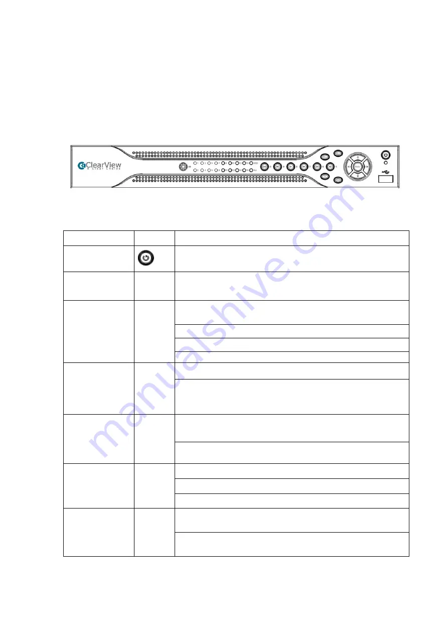
The front panel is shown as below. See Figure 2-1.
Figure 2-1
Please refer to the following sheet for front panel button information.
Name
Icon
Function
Power button
Power button, press this button for three seconds to boot up or
shut down DVR.
Shift
Shift
In textbox, click this button to switch between numeral,
English(Small/Capitalized),donation and etc.
Up/1
Down/4
、
Activate current control, modify setup, and then move up and
down.
Increase/decrease numeral.
Assistant function such as PTZ menu.
In text mode, input number 1/4 (English character G/H/I)
Left/2
Right/3
Shift current activated control,
When playback, click these buttons to control playback bar.
In text mode, input number 2(English character A/B/C)/3(English
character D/E/F)
.
ESC
ESC
Go to previous menu, or cancel current operation.
When playback, click it to restore real-time monitor mode.
Enter
ENTER
Confirm current operation
Go to default button
Go to menu
Record
REC
Manually stop/start recording, working with direction keys or
numeral keys to select the recording channel.
Click this button for at least 1.5 seconds, system can go to the
Record interface.
Содержание Panther-16HP
Страница 1: ...Standalone DVR Quick Start Guide Version 1 1 0 ...
Страница 3: ...iii 3 3 Main Window 33 ...
Страница 29: ...24 Please refer to the following figure for detailed information Figure 2 17 Figure 2 18 ...
Страница 40: ...HD AVS Standalone DVR User s Manual V1 3 0 ...
Страница 46: ...vi APPENDIX E COMPATIBLE SWITCHER 215 APPENDIX F COMPATIBLE WIRELESS MOUSE LIST 216 APPENDIX G EARTHING 217 ...
Страница 109: ...61 Figure 4 53 Figure 4 54 4 10 1 3 Encode ...
Страница 135: ...87 Figure 4 81 Figure 4 82 Figure 4 83 ...
Страница 141: ...93 Figure 4 89 Figure 4 90 ...
Страница 142: ...94 Figure 4 91 Figure 4 92 ...
Страница 145: ...97 Figure 4 96 Figure 4 97 ...
Страница 151: ...103 Figure 4 106 Figure 4 107 4 10 4 1 2 2Trigger Snapshot ...
Страница 169: ...121 Figure 4 129 For digital channel the interface is shown as below See Figure 4 130 Figure 4 130 4 10 5 5 ATM POS ...
Страница 179: ...131 Figure 4 141 ...
Страница 254: ...206 448K 196M 512K 225M 640K 281M 768K 337M 896K 393M 1024K 450M 1280K 562M 1536K 675M 1792K 787M 2048K 900M ...


