

© Safe Fleet | 2023
Part #: 700-1174 R6
Information is subject to change without notice.
Please check
https://community.safefleet.net
for the latest version and additional documentation.
NH16K NVR System
Quick Installation Guide
This Quick Installation Guide is a basic install and setup reference for the recorder. Review it completely before proceeding.
The NH16K system
also requires installation of the network switch
(Safe Fleet NS18POE16 - see the
16-Port Network Switch Installation Guide
, part #700-1156).
Third-party switch gear is not supported, and may inhibit proper operation
. Please visit the Safe Fleet Community at
https://community.safefleet.net
for the latest product details and full installation instructions.
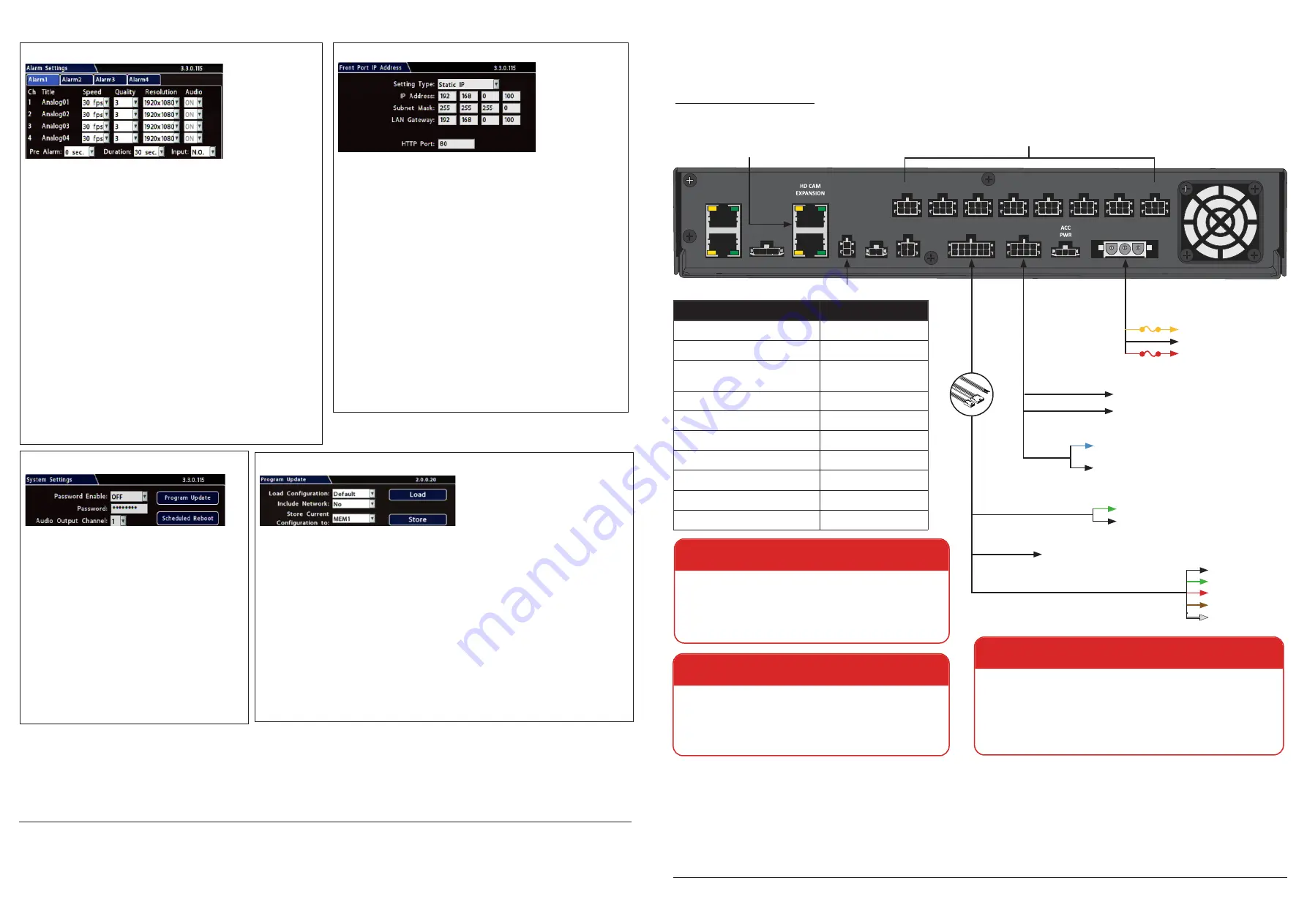
Typical System Setup:
The NH16K supports a maximum of 16 channels:
Optionally connect:
To...
PoE Injector Kit
ACC PWR
GPS Receiver*
1
GPS Input
RGY Button*
2
Adapter Harness (1x5
Microfit connector)
Smart-Reach Lite (Wi-Fi)*
3
12V POE WIFI Input
Smart-Reach Cellular Modem*
3
MODEM Input
Laptop*
3
LAN Input (
front
)
Portable Video Monitor*
4
VIDEO OUT (
front
)
External G-Sensor
G-SENSOR Input
Alarm Switch
ALARM 2 Input
SD Card*
5
SD Card Slot (
front
)
1. For speed tracking, use a GPS receiver.
2. The RGY Button is optional, and requires the WT2 adapter
harness and the RGY extension harness (part# 060-1197).
3. An optional Smart-Reach Wi-Fi bridge or Smart-Reach Cellular
modem can be connected to the rear panel 12V POE WIFI/
MODEM ports, and a laptop can be used from the Ethernet
output on the front panel.
4. An optional Video Monitor can be used from the video outputs
located on the front panel.
5. Use Safe Fleet-approved cards only.
6. Wake/Signal 6 Input, active high (5-32V edge-triggered)
Notes (*)
Black - Battery Negative
Yellow - Vehicle Ign +12V
Red - V12V
WARNING: Cable and harness slack
Ensure cables and harnesses have slack and can move
freely with the recorder without being pulled to the side
or away from the connector. A 4-inch diameter loop is
normally sufficient.
WARNING: Automatic drive formatting
Storage media might not be recognized on recorders running
different firmware. By design, unrecognized media automatically
formats when inserted into a recorder, so recording can
commence. Customers who swap cartridges between recorders
should ensure each recorder has the same firmware version.
WARNING: Noise suppression
Do not use the output of a noise suppression solenoid
as a recorder ignition or power source. If no true ignition
or power source can be readily found, consult the bus
schematic bus or manufacturer to locate a proper source.
Harness
WT2
sup-
ports RGY button
and extn. harness
pkg.
HEDM20
POWER
20 ft./6.1m
Power harness:
060-1136
Power harness/fuse pkg.:
PH1X3UM20
060-0656
060-1059
MODEM
POE WIFI
G-SENSOR
CTRL
ALARM 2
GPS
SIGNALS
EXPANSION
POWER
CAM 1
1
2
CAM 2
CAM 3
CAM 4
CAM 5
CAM 6
CAM 7
CAM 8
16 IP Cameras from the
NS18POE16 Network Switch
8 Standard Resolution and/or High Definition Cameras
Adapter
Harness*
2
5 wires
RGY BUTTON
:
065-1010
(Optional)
1x5 Microfit
3 wires
1A
20A
Rear Vision System (Optional)
Reserved
2x3 Microfit
1x4 Microfit
2 wires
WAKE (Optional)
Green - Input: Wake/Signal 6*
6
Black - Battery Negative
SIGNALS
Black - Left Turn
Green - Stop
Red - Brake Signal
Brown - Warning
White - Right Turn
Network Switch Control Cable
:
2 wires
DIGITAL OUTPUT (
Optional
)
Blue - Active H (12V 150mA source)/
Active L (ground 350mA sink)
Black - Ground
20 ft./6.1m RGY extn.
harness:
060-1197
Expansion
Harness:
Technical Support
Toll free telephone 1.844.899.7366
Email: [email protected]
Warranty
For full warranty information, visit
www.seon.com/documents/Seon-Warranty.pdf
.
Basic NVR configuration
(
continued
)
Step 5. Alarms
From the Configuration menu, select
Alarms & I/O
Alarms
.
Alarm
: Alarms 1 and 2 can be triggered by an event/alarm button. Alarms
1-4 can come from Signals or other features such as speed or GPS.
Pre Alarm
:
Optionally, select a time period prior to an alarm being triggered
where recorded video and metadata are included with protected alarm data,
which won’t be overwritten. For more information, see Recording Settings
(Advanced) in the
NH16K Install and Config Guide
.
Duration
: Set the Duration for how long the NVR will record video flagged as
an alarm for each alarm input.
Input
: Applies to Alarms 1 and 2 only. Choose N.O. (Normally Open), N.C.
(Normally Closed), or N.H. (Normally High) depending on the switch type
used.
Speed
(frames/second),
Quality
, and
Resolution
: For each alarm, select
higher settings for better video while the alarm is recording.
Note:
Speed, Quality, and Resolution settings are only adjustable for specific
camera/device types. For details, see the
NH16K Install and Config Guide
.
Audio
: When audio is normally disabled,
set ON to enable audio for the
Alarm Duration period.
Click
Back
twice to save settings and return to the Configuration menu, then
click
Network
.
Step 7. System
Password Enable
: Leave OFF unless instructed
otherwise.
Password
: If enabled, this password is required for non-
Admin users to access the local NVR UI.
Audio Output Channel
: Select the audio channel that will
be available from the audio RCA port on the front of the
NVR.
Diagnostic Indicator
: If installing an RGY Button or RGY
Illuminator, select which one.
Language
: Select the language for the local NVR UI and
vMax Web.
Scheduled Reboot/Reboot Now
: Configure a time-of-day
for the recorder to reboot, or reboot immediately.
Click
Program Update
.
Step 8. Load Config File, Format Drive
Store Current Configuration
: Select
USB Device
as the file-saving destination. Plug a USB
memory device into the front of the NVR. Click
Store
to save the file on the USB memory device.
Load
: For details on uploading configurations to the recorder, see “NVR Configuration Uploads”
in the
NH16K Install and Config Guide
.
Update
: Delivers a firmware update to the recorder, network switch, or a connected IP camera
from an image file stored on a USB device. Select
DVR
,
Switch
, or
IPC,
then click
Update
and
navigate to the image file:
DVR
or
Switch
: The device reboots when updates are done.
IPC
: Click a numbered tab at the top of the screen to update firmware on the camera
connected to the selected port, then click
Update
.
Format
: Format the hard drive and SD card (if installed) when the configuration is complete and
tested and before final delivery of the installation to the customer.
Click
Back
twice to save settings and return to the Configuration menus.
Advanced Configuration Options
Alarms & I/O
Signals
: configure signal inputs and the actions they generate.
Alarms & I/O
Speed
: record vehicle speed or trigger notifications for excessive speed.
Network
User Levels
: create NVR user logon profiles and assign passwords to enable remote access with various permission levels.
For more information about these settings, please see the
NH16K Install and Config Guide
on the Safe Fleet Community Web site.
Step 6.
Network
From the Configuration menu, select
Network
IP Addresses
Front
.
Setting Type
: Leave at default
Static IP
setting.
IP address
: used to communicate with the NVR over the network with
vMax Web. Leave at default setting unless instructed by the customer.
HTTP Port
: typically, leave set to
80
unless instructed by IT personnel.
Notes:
If Smart-Reach Mobile Wi-Fi equipment or a Smart-Reach Cellular
modem is installed, click
Network
I
P Addresses
Wifi/Modem
to
configure communication parameters. For more information, see the
NH16K Install and Config Guide
and the Smart-Reach documentation
available on the Safe Fleet Community.
If the IP information is changed and saved in a configuration file for
upload to other NVRs, their settings will have to be updated as well. For
more information, see “NVR Configuration Uploads” in the
NH16K Install
and Config Guide.
If the system uses Commander or Depot Manager
: contact Technical
Support for assistance with setup.
Click
Back
to save settings and return to the Configuration menu, then
click
System
.


