background image

H.264 4/8/16-Channel Networkable DVRs  
Installation and Setup Guide

Products: DMR90U, DMR91U, DMR92U

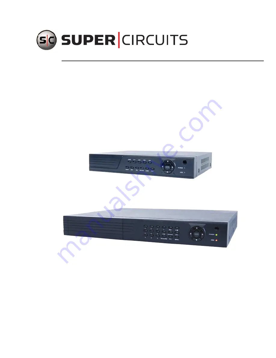
DMR90U 4-Channel DVR

DMR91U 8-Channel DVR and DMR92U 16-Channel DVR

PLEASE READ THIS MANUAL BEFORE USING YOUR SYSTEM, and always follow the 

instructions for safety and proper use. Save this manual for future reference. 

DMR9xU_RM

Summary of Contents for DMR90U

Page 1: ... Guide Products DMR90U DMR91U DMR92U DMR90U 4 Channel DVR DMR91U 8 Channel DVR and DMR92U 16 Channel DVR PLEASE READ THIS MANUAL BEFORE USING YOUR SYSTEM and always follow the instructions for safety and proper use Save this manual for future reference DMR9xU_RM ...

Page 2: ...of certain product applications such as the making transmission or recording of video and or audio signals of others without their knowledge and or consent We encourage you to check and comply with all applicable local state and federal laws and regulations before engaging in any form of surveillance or any transmission of radio frequencies Microsoft Windows and Internet Explorer are either regist...

Page 3: ...e remote control and mouse 15 SECTION 3 DVR Setup 17 3 1 Login to the DVR 17 3 2 Configuring the system 18 3 2 1 Setting the screen language and video system format 19 3 2 1 Setting the system time 19 3 2 2 Change the Admin and user1 passwords 21 3 2 3 Add users to the system 22 3 2 4 Set HDD overwrite option 23 3 3 Record configuration settings 24 3 4 Video configuration settings 26 3 4 1 Video s...

Page 4: ...ng KWeye in Android 54 6 2 Set up access to a DVR 54 6 3 Using KWeye 55 SECTION 7 DVR System Menus 57 7 1 Menu tree 57 7 1 1 Tool Bar 58 7 1 2 Menu options 59 7 2 System menu 60 7 2 1 Language 60 7 2 2 Video System 60 7 2 3 Time Setup 60 7 2 4 User management 61 7 2 5 VOLUME 64 7 2 6 HDD 64 7 2 7 Maintenance 65 7 2 8 Information 66 7 3 Record 66 7 3 1 Record Channel 67 7 3 2 Record 67 7 3 3 Bit ra...

Page 5: ... 76 7 6 1 OUTPUT 76 7 6 2 DURATION 76 7 6 3 BUZZER 76 7 6 4 PRERECORD 76 7 6 5 EXCEPTION 77 7 6 6 I O Alarm 77 7 6 7 Motion Detection 78 7 7 PTZ 80 7 7 1 Channel 80 7 7 2 Protocol 80 7 7 3 Baud Rate 80 7 7 4 Data Bit 80 7 7 5 Stop Bit 81 7 7 6 Parity 81 7 7 7 Address 81 SECTION 8 Cleaning 82 APPENDIX A Off loadedVideo Files 83 APPENDIX B Troubleshooting 84 APPENDIX C DVR Compatible HDDs 88 APPENDI...

Page 6: ...vi www supercircuits com ...

Page 7: ...iPad and iPod Touch Google Android Symbian Windows Mobile and Blackberry smartphones apps that let you monitor your home or business on the go from anywhere These DVRs are usually pre configured with and internal hard disk drive HDD by request of the purchaser which retains the warranty on the unit However if the DVR enclosure is opened by the purchaser necessary to install a an HDD the warranty f...

Page 8: ... Resource Pack with smartphone applications Mounting bracket for mounting an internal hard disk drive if no HDD is pre installed DMR92U Your DMR92U DVR includes DMR92U DVR unit Remote Control Mouse Power adapter with cord for standard 120 VAC outlet 8 channel audio RCA cable adapter 2 DVR Quick Guide CD Resource Pack with smartphone applications Mounting bracket and screws 8 for mounting an intern...

Page 9: ...d s CCTV analog security cameras The DMR9xU series DVRs support a large number of cameras Microphones for audio monitoring optional Extension cables for the cameras with cable adapters if needed to connect to the DVR BNC video terminations RCA audio terminations RS485 extension cable for PTZ cameras Consult your local electrical codes for gauge and shielding requirements Powering equipment to supp...

Page 10: ...e or where these influences can be minimized Ease of installation The camera must be installable at the location considering mounting hardware requirements temperature dust moisture etc About weatherproof cameras Weatherproof cameras can be mounted in any open area such as on a telephone pole or on the side of a building However for best results we recommend you mount your cameras in a sheltered a...

Page 11: ...ur ownHDD butopeningtheenclosertoinstallitwillvoidthewarranty Referto Appendix C DVR Compatible HDDs for more information 2 2 1 DVR placement Your monitoring and recording equipment is central to constant surveillance and the reliable capture of video evidence Supercircuits strongly suggests that it be installed in a secure location with access limited to authorized personnel DVRs generate heat an...

Page 12: ...channel 1 2 3 or 4 Enter Press to confirm a menu choice Infrared Sensor Sensor for the remote control MENU Opens the main menu window ESC Press to exit any active window REC Use to start and stop manual recording BACKUP Opens a video search and playback menu u II When a recorded file is selected press this button to play then press it again to pause playback PTZ Used for pan tilt zoom control of c...

Page 13: ... audio input to audio channels 1 2 3 and 4 CH1 CH4 VIDEO IN BNC video input to video channels 1 2 3 and 4 MAIN OUT BNC composite video output to display device 75Ω 1V p p MAIN OUT VGA Standard VGA output to a display device such as a computer monitor LAN Standard RJ45 Ethernet 10BaseT 100BaseT port with auto detect ALARM IN ALARM OUT RS422 RS485 Use these connectors to attach external sensor devic...

Page 14: ...ff To power off the DVR Enter Press to confirm a menu choice Infrared Sensor Sensor for the remote control Remote control is not provided Status LEDs Status LEDs for power and HDD activity tqpu Use these buttons to navigate through the menu system Generally use the tubuttons to move to selection boxes and use the qpto select submenu parameters MENU Opens the main menu window REC Use to start and s...

Page 15: ...witch POWER DC 12V 12 VDC adapter power input connector Alarm In Out RS485 Terminals Alarms in 1 4 terminations For connecting to external sensor device each alarm has one input pin Connect positive output pins of the alarm device to the inputs Alarm In on the DVR Connect ground output pins of the alarm device to the DVR Ground slots G Multiple devices can be connected to one ground slot Alarms ou...

Page 16: ... device such as a computer monitor AUDIO IN 9 16 SPOT AOUT Connector for input adapter for channels 9 16 audio for video channel inputs 9 16 and Spot camera out for spot video to a monitor DC 12V Connect to 12 VDC power adapter Alarm In Out SENSOR RS485 Terminals Alarms In 1 16 terminations For connecting to external sensor device each alarm has one input pin Connect positive output pins of the al...

Page 17: ...ble To UPS 120 VAC Power DVR Power Adapter To Alarm In Out PTZ Devices Camera Power Source Mouse Camera DVR Microphone Monitor To Audio Inputs Camera Drop Cable BasicSystemInterconnectionDiagram NOTE Power cabling shown in the previous diagram is recommended for 4 channel systems with CD33W 2 series cameras 8 and 16 channel systems include an RCA to DB 9 audio input adapter cable s and back panel ...

Page 18: ...ed TX TX RX RX DMR91U The DMR91U provides four alarm inputs 1 4 with one ground terminal labeled G One normally open alarm output labeled NO and COM RS485 terminations are labeled A and B for RS485 A and RS485 B respectively DMR92U The DMR91U provides 16 sensor inputs The lower row of terminations are for sensor inputs for alarms 1 12 left to right Sensor inputs 13 through 16 are in the upper row ...

Page 19: ... display connect it to the MAIN OUT VGA connector If using the MAIN OUT BNC connector to drive a display such as a TV attach the appropriate cables between the MAIN OUT BNC and your display device 4 If you are installing a system a Connect a camera power adapter to the DVR end of each video power extension cable then plug the power adapter into a standard 120 VAC power source through a UPS or surg...

Page 20: ...stem monitor 6 Power on the DVR using the POWER switch on the backpanel A startup Loading screen will appear on the display After a few seconds the screen will change to the camera view screen Note The images you see from your cameras may be different from those shown here 2 4 Adjusting the camera Adjust your camera to produce the best performance While observing video from your camera use the doc...

Page 21: ...SC Displays exits the main menu 6 Lock If the password is enabled press it to logout the system 7 Numerical Button Use buttons 1 2 3 or 4 to select the channel to display 8 REC Start or Stop manual recording 9 Quad Press this button to switch display modes from single channel display to a multi channel display 10 Mute Not used 11 Spot View Press to enable auto sequencing 12 Fast Forward Fast forwa...

Page 22: ...ion reverse function I Slow play function I frame play function Play function and X exit function In the VIDEO VIDEO SETUP COLOR SETUP configuration window you can left click to adjust color control bar and screen control bar In the main menu sub menu or playback view left click x to exit close the current menu In the ALARM MOTION MD AREA configuration window left click an area segment to select d...

Page 23: ...eldisplaywillbean8 splitscreen onesplitforeachchannel 3 1 Login to the DVR Initially two access accounts are provided in your system Admin and user1 With the Admin login you can make configuration changes to the system create user accounts and passwords and control the privileges allotted to each account With the factory default user1 account login you cannot make configuration changes or create a...

Page 24: ...n click the confirm entry icon 5 Click the a check mark icon in the lower right corner of the window to confirm your entry and enter the login information A tool bar icon strip will appear at the bottom of the screen 3 2 Configuring the system Basic system configuration settings include setting the screen language video system format system time creating users initializing the hard disk drive HDD ...

Page 25: ...ylock Mute On Off ToolBar 5 Click the Settings button on the Tool Bar 3 2 1 Setting the screen language and video system format 6 In the Settings window SYSTEM tab click the q icon at the right end of the LANGUAGE line Select click the screen language you prefer from the dropdown list 7 If the VIDEO SYSTEM option does not indicate NTSC click the q icon at the right end of the VIDEO SYSTEM line the...

Page 26: ... prefer 12 hour or 24 hour 5 Click the entry on the TIME line Click the t or u icons to highlight a digit of the current time then click the number value of the digit To complete the entry click the button 6 If you selected a 12 hour time format click the q icon on the line below the TIME entry then select either AM or PM 7 On the DST line click the icon to open the DST ON OFF option window If you...

Page 27: ...88888 user1 666666 To change these passwords 1 With the system powered on right click twice on the desktop or press the menu button on the front panel twice then log into the system as the Admin if a password login is required 2 Click the Settings icon on the Tool Bar to open the SYSTEM tab window 1 On the USER line click the icon to open the USER MANAGEMENT window 2 On the CHANGE PASSWORD line cl...

Page 28: ...ers to the system 1 On the SYSTEM tab USER line click the icon to open the USER MANAGEMENT window 2 In the USER MANAGEMENT window click the icon on the ADD USER line 3 Click the entry field on the USER NAME line to open a virtual keyboard Click the letters and numbers to enter a username then click the icon to close the keyboard 4 Enter both the PASSWORD and CONFIRM PASSWORD fields with a password...

Page 29: ...reen then click the Confirm button in the Note window 11 Press the MENU button on the front panel to return to the USER MANAGEMENT window then press the MENU button again to return to the SETTINGS window SYSTEM tab 3 2 4 Set HDD overwrite option 1 On the SYSTEM tab HDD line click the icon to open the HDD MANAGEMENT window 2 Click the q icon at the right end of the OVERWRITE line From the dropdown ...

Page 30: ...le for each channel are setup through the Record tab 1 Click the Settings icon on the Tool Bar to open the SYSTEM tab window 2 Click RECORD to open the RECORD settings menu 3 Click the q icon at the right end of the CHANNEL line From the dropdown list select the number of the camera channel you want to setup or select ALL to configure all channels with the same settings 4 Click the q icon at the r...

Page 31: ...the week either by motion sensing continuous recording or not recording See Scheduled recording below 10 If you are configuring the camera channels differently repeat this procedure for the other camera channels Scheduled recording If the RECORD MODE SCHEDULE is selected 11 Click the icon on the RECORD tab to open the RECORD SCHEDULE SETUP window 12 Click the q icon at the right end of the CHANNEL...

Page 32: ...ndow 2 Click VIDEO to open the VIDEO settings menu 3 Click the q icon at the right end of the CHANNEL line From the dropdown list select the number of the camera channel you want to setup or select ALL to configure all channels 4 Initially camera channels are named CH1 CH4 You can change the name of the channel by clicking on the entry field on the NAME line to open a virtual keyboard Use the keyb...

Page 33: ...m icon a in the lower right corner of the screen then click the Confirm button in the Note window 9 If you setup the record schedule for a single channel repeat this procedure to setup the other camera channels 3 4 1 Video setup The VIDEO SETUP menu provides configuration settings for the monitor screen resolution sequential live view settings and video blocking 1 Click the Settings icon on the To...

Page 34: ...rom each camera in full screen Video blocking For security or privacy reasons some areas of the video fields of view are blocked To setup the blocking 1 In the VIDEO SETUP menu click the q icon at the right end of the CHANNEL line then select a video channel number from the dropdown list 2 On the VIDEO SETUP AREA COVERED line click the icon Video from the camera will appear in full screen mode 3 B...

Page 35: ...CH1 Volume Click System Settings System Volume to open the Volume setting window With a normal sound volume level in the environment of the microphone drag the slider left or right to decrease or increase the volume level RECORD menu AUDIO Open the RECORD menu In the AUDIO option select OPEN or CLOSED OPEN indicates that the audio recording for all channels is enabled CLOSE indicates that audio re...

Page 36: ...DURATION line From the dropdown list select either 30 SEC 5 MIN This option sets the recording time length after an alarm recording is activated 4 Click the q icon at the right end of the BUZZER line From the dropdown list select either OFF or 5 SEC 60 SEC This option sets the buzzer sounding time when the alarm is triggered 5 Click the q icon at the right end of the PRERECORD line From the dropdo...

Page 37: ...OSS label to enable this alarm When a video signal from a channel is not detected this feature will sound the buzzer and place the Video Loss label in the channel LIVE view window 10 After configuring your network settings click the confirm icon a in the lower right corner of the screen click the Confirm button in the Note window 11 Press the MENU button on the front panel or right click anywhere ...

Page 38: ... may be appropriate for detecting only cars that pass by This setting is dependent on the what you want to detect and usually requires testing to find the best value 5 Click the icon on the MD AREA line to specify the areas where of the screen where motion should be sensed Defining only these areas and ignoring other areas of the field of view improves the performance of the DVR The Motion Detecti...

Page 39: ...e buzzer when motion is detected 9 Check the box to right of the PRERECORD label to add the previous 5 seconds of video from the camera to the motion detection recording 10 Check the box to right of the EMAIL label to send an email when motion is sensed To use this feature the EMAIL configuration settings in the NETWORK tab must be configured 11 After configuring your motion detection settings cli...

Page 40: ...al home network includes router one or more computers and a broadband modem for access to an internet service provider ISP and the internet The DVR attaches to the network like a computer except that it has preset IP address settings that must be configured for your network DVR Router Broadband Modem Home Network Computer Web Connected Computer DVR Monitor Home Network Setting up the DVR on the ho...

Page 41: ...hout conflicting with other devices configure the network settings of your DVR before physically connecting it to the network Network conflicts occur when two devices on the network have the same IP address The screens shown here were taken from a Windows XP system 1 Determine the IP address subnet mask and default gateway of your home computer PC and record it in Table 1 To get this information d...

Page 42: ...address of your PC up to the third last period Using the example shown above in the screen capture of ipconfig this number would be 192 168 1 b After the third period choose any number between 1 and 255 that is different from the one in your PC s IP address 168 As a first try let s choose 100 which will form the IP address 192 168 1 100 c Next use the ping command in the DOS window to see if that ...

Page 43: ... a reply as shown above try the ping with another number between 1 and 255 until one is found that responds with the Request timed out message Use this IP address with your DVR and enter it into Table 1 f In table 1 copy the PC s Subnet Mask and Default Gateway entries into the DVR s Subnet Mask and Default Gateway cells 3 At your DVR click the System Settings icon on the Tool Bar to open the SYST...

Page 44: ...f the TYPE line From the dropdown list select either DHCP PPPOE or STATIC for the IP network setup If you select DHCP or PPPOE the DVR will acquire its network settings automatically If you select STATIC you can configure your network settings manually by clicking on the entry field and using the virtual keyboard to enter data See the following screen capture ...

Page 45: ...ht click anywhere to return to the SETTINGS menu 10 At the SETTINGS menu click the SYSTEM tab then click the icon on the MAINTENANCE line 11 Click the icon on the REBOOT line then follow the on screen prompts to reboot your DVR 12 Connect an Ethernet cable between the LAN port on the back of your DVR and any open port on your router 13 At your PC use the ping command with your DVR s IP address to ...

Page 46: ...s in IE are modified and an additional software is installed 1 At your PC load IE 2 Open the IE Tools pull down menu and select Internet Options Click the Security tab 3 Click the Custom Level button In the Settings list change the following settings to Enable Automatic prompting for ActiveX controls Initialize and script ActiveX controls not marked as safe for scripting Script ActiveX controls ma...

Page 47: ... Apply then click OK to close the window NOTE If yourcomputeroperatingsystemisWindows VistaorWindows 7 UserAccountControlcaninterferewiththenormaloperation oftheDVRuser interface TodisableUAC opentheControlPanel UserAccount UserAccountwindow clearthe UseUser AccountControl UAC tohelpprotectyourcomputer checkbox thenclickOK Acomputerrestartmayberequired ...

Page 48: ...RL IEmaypromptyoutoloadtheChineseSimplifiedlanguagepack YoucanclickInstallorCancel Ifyouclick Cancel the messagewillreappearagainwhenyoulogoutandlogin 5 During the first connection to the DVR a security warning to install software appears Click Install and follow the on screen instructions to complete the installation 6 When the Login screen opens in the browser enter the administrator USER ID and...

Page 49: ...n in the lower left corner of the screen NOTE The followingsectionsprovideagenericprocedureforsettingupa4 channelsystemwithaDMR90UseriesDVR Ifyouaresetting upan8 or16 channelsystem thedisplays youseemaybeslightlydifferent Forexample ifyouhavean8 channelDVR the initialDVR camerachanneldisplaywillbean8 splitscreen onesplitforeachchannel SECTION 4 NETWORKING YOUR DVR ...

Page 50: ...r efficient data transfer to occur This procedure requires that the network router be configured for port forwarding Only general instructions for setting up this capability are included here NOTE SupercircuitsprovidescompletetechnicalsupportforviewingyourDVRwithinyourLAN Howeveroursupportteamcannot assurecomplete technicalassistanceforproducts fromothermanufacturers suchasroutersandmodems Referto...

Page 51: ... go to http www whatismyip com from a PC on the same network LAN as your DVR The IP address displayed is the IP address you will use to log in remotely Keep this in your records Skip to step 6 Static IP Address 4 If you have a dynamic IP address it is convenient and recommended to use a dynamic name server service such as http www dyn com a free service to setup a remote connection with a fixed ho...

Page 52: ...46 www supercircuits com SECTION 4 NETWORKING YOUR DVR ...

Page 53: ...u can access it with Microsoft Internet Explorer IE using placing the IP address and Webport of the DVR in the IE URL field For example the URL address HTTP 192 168 1 100 8090 uses an IP address of 192 168 1 100 and a webport number of 8090 If you are accessing your DVR from the internet the network modem router where your DVR is installed is 77 67 214 84 and your DVR is configured on the router p...

Page 54: ...our channels at the same time see above screen capture only one channel on the screen or expand one channel to fill your monitor screen Stop View Click the Stop View icon to stop viewing live video Snap Click the Snap icon to capture a photo of the selected video channel To select a video channel on a multi channel display click the image The selected channel is framed with a blue border The photo...

Page 55: ...reen Use the play control buttons below the view window to control the playback To download the video clip to your computer click DOWNLOAD The clip will be saved in the location specified in the LOCAL SETTING screen the download progress will appear at the bottom of the view window and the path and name to the video file will be displayed with the download is complete 4 Click on another file to pl...

Page 56: ...ment for more information After making changes to a Remote setting menu click the SETUP button at the bottom of the window to commit the changes Click the Ticon in the upper right corner to close the Remote Setting window before selecting another screen or window 5 5 Local setting In the Local Setting window you can specify the locations on your computer where you want to save the recordings frame...

Page 57: ... DVRs Click the Ticon in the upper right corner to close the Remote Setting window before selecting another screen or window 5 6 Logout Clicking LOGOUT returns you to the USER LOGIN screen SECTION 5 ACCESSING YOUR DVR WITH A WEB BROWSER ...

Page 58: ...f KWeye with the Apple and Google smartphones For more information go to iPhone iPad and iPod touch http itunes apple com us app kweye id412413785 Android phones https market android com details id com KWeye For other smartphones contact Supercircuits Support at 1 800 335 9777 To use this application your DVR network must be setup to allow access from the Internet 6 1 Installing KWeye 6 1 1 Instal...

Page 59: ... apple com itunes A computer restart may be required Open iTunes Click the iTunes Store item in the list on the left then login to your iTunes Store account If you don t have an iTunes Store account follow the on screen instructions to create one In the Search Store field in the upper right corner of the screen enter kweye After KWeye is found click the Free App button then click Buy in the popup ...

Page 60: ...he application is found click on the KWeye icon to display details of the app To install KWeye click Install and follow the on screen instructions 6 2 Set up access to a DVR Usage and functionality of the KWeye app is the same on both iPhone and Android phones However the screens vary slightly between the two systems To use KWeye Tap the KWeye icon to open the app The KWeye splash screen will appe...

Page 61: ...splay the UserName and Password fields After completing the entries in the Settings menu tap the Back button to test the settings and connect to your DVR When connecting to your DVR the Device Info settings will be logged in the History screen for easy retrieval 6 3 Using KWeye If KWeye is not running tap the KWeye icon to open the app The KWeye History screen will appear In the History screen tap...

Page 62: ...e channel button is not shown tap a Switch Channel Group icon next group or previous group to change the Select Channel buttons until the channel number is shown then tap the button for the channel Rotate the phone 1 4 turn for a landscape view of the channel To restore the app control buttons orient the phone for a portrait view To exit the application press the smartphone Home or Back button ...

Page 63: ... Margin Video Setup Device ID Password Add Users Change Password Delete User Set Permissions Remote View Network Network DDNS Email Mobile IP Address Other Settings Alarm PTZ Output Duration Buzzer Prerecord Exception Motion I O Alarm Motion Channel Protocol Baud Rate Data Bit Stop Bit Motion Parity Address System Settings Play Manual Record Keylock Mute On Off Auto Sequence PTZ Ezoom Advanced VGA...

Page 64: ...audio mute Keylock If the password is enabled click KEYLOCK to logout of the system Auto Sequence Click to enable auto sequencing the channels with images will be in sequence channel 1 channel 2 channel 3 channel 4 channel 1 Channels without images won t appear in the sequence To interrupt auto sequencing press any button or click the mouse while in auto sequence mode EZoom Click to enter zoom mod...

Page 65: ... the left and the corresponding changeable or non changeable values are represented in the fields to the right You can Select the values from the list toggling the preset data by pressing the arrows on the side of the field Select the values from the drop down list open the drop down list by clicking the down arrows on the side of the field Input the required data after entering a customized windo...

Page 66: ...a mode 7 2 3 Time Setup Click Time System settings System Time to open the Time setup menu DATE Set up system date using the number keypad DATE FORMAT Click the down arrow to switch the date format Options YY MM DD MM DD YY TIME FORMAT Click the down arrow to switch the time format Options 12 HOURS to 24 HOURS TIME Set up the system time using the number keypad on the remote control DST Daylight s...

Page 67: ...d After turning on password and clicking the check button in the lower right corner of the window exit the system and login again to manage other users DEVICE ID Set Number to identify device The default name is 000000 PASSWORD Change the password The following settings can be configured only by a user with administrative privileges ADD USERS To add new user enter a new username and password Passw...

Page 68: ...he username whose password you want to change then enter the old password the new password and the new password again in the Confirm Password field DELETE USER In this window select the user you want to delete then click the check button in the lower right corner of the window ...

Page 69: ...etting If password verification is enabled marked ON i e you must login with a password you can setup seven user passwords and an administrator password Note When Password is enabled login to the system as an admin to manage user settings The administrator s name Admin cannot be changed Initially two users exist Admin and User1 The default password for Admin is 888888 and the default password for ...

Page 70: ...t time the system will restart after the HDD is formatted TOTAL FREE Indicates total space available on the HDD FREE TIME Indicates remaining recording time of the HDD OVERWRITE Includes CLOSE AUTO 1 HOUR 3 HOURS 1 DAY 2 DAYS 7 DAYS 30 DAYS and 90 DAYS CLOSE the recording stops when the hard disk drive is full It will continue recording if overwrite is enabled AUTO the recording continues and over...

Page 71: ... d Eject the thumb drive from the Windows PC 2 Insert the thumb drive into a USB port on the DVR then a Click the icon on the SYSTEM UPDATE line b Wait until the DVR recognizes the thumb drive c Press Enter to upgrade the firmware The progress of the system upgrade will be displayed After completing the upgrade the DVR will restart NOTE The system upgrade usually requires more than two minutes to ...

Page 72: ...tion display This display includes device type software version release date import parameter and export parameter Use Export Parameter to save that information to a USB disk Parameter information must be exported before it can be imported restored 7 3 Record To open the Record menu move the cursor to RECORD the icon will be highlighted when selected then press Enter You can use the direction keys...

Page 73: ...n of each channel recorded can be adjusted independently 7 3 5 Frame Rate You can set the recording frame rate frames per second fps for the current channel The higher the record frame rate the smoother the movement you will see in playback mode The frame rate of each channel can be adjusted independently For PAL video output format the default system resolution is CIF and the default frame rate i...

Page 74: ...hen motion is detected and or an alarm is triggered NOTE Manual recording continues until stopped by the operator It overrides all settings CHANNEL You can select all channels or just one channel There are three modes for recording ALARM NORMAL and NO RECORD Different colors indicate different recording modes Red indicates alarm record green indicates normal record gray indicates no recording To s...

Page 75: ...scroll to the check button in the lower right corner of the window then press ENTER 7 4 Video Move the cursor to VIDEO the icon will be highlighted when selected then press ENTER to enter the video menu You can use the direction keys and cursor to change the options 7 4 1 Video Channel Select the channel to setup 7 4 2 Name You can assign a name to each channel The channel name can be up to 9 char...

Page 76: ...e video color adjustment tool With this feature you can adjust camera color attributes for the best image rendition By default the values are set to a midpoint 31 Press u t key or drag the set bar to adjust the video attributes Clicking DEFAULT button to reset the color parameter values click the check button to save your settings 7 4 7 Record Time You can define which information will be recorded...

Page 77: ...ered Set privacy area Up to four areas of privacy can be configured for each channel Privacy areas appear as black rectangles over portions of the video image that are setup as private 7 5 Network Move the cursor to NETWORK the icon will be highlighted when selected and press ENTER to open the Network configuration window In this window you can configure network DDNS email and mobile access settin...

Page 78: ...nternet STATIC network settings When selecting STATIC allocation you must enter the IP address subnet mask gateway and a web port MEDIA PORT Port used to transfer video data from the DVR to a client WEB PORT Sets up the port for the IE browser via HTTP The default web port is 80 SETUP PORT This port number is fixed at 8000 It cannot be changed DNS Press ENTER then enter the domain name sever addre...

Page 79: ...ed to 8088 and the DVR IP address is 192 168 15 145 the URL for the DVR across the same subnet is http 192 168 15 145 8088 SETUP PORT This port is fixed and cannot be changed It is set to 8000 MAC ADDRESS The hardware address of the network interface circuitry This address fixed and cannot be changed PPPOE user and password Enter the PPPOE username and password provided by your internet service Cl...

Page 80: ...f a DDNS server is available select ON SERVER Select one of the three providers 3322 dyndns or perfecteyes HOST NAME Enter the name of the host server USER NAME Enter the name of the user establishing the DDNS server account PASSWORD Enter the password associated with the USER NAME 7 5 3 Email Setup Move the cursor to EMAIL SETUP and press ENTER to open the Email Setup menu ...

Page 81: ...sender s email address The email address should be consistent with the server you use For example when you use the email address abc gmail com the corresponding server should be smtp gmail com RECEIVER This indicates the recipient email address The email address is used to receive images transmitted after a motion detection alarm by the DVR 7 5 4 Mobile Monitor Move the cursor to MOBILE then press...

Page 82: ...d Options include OFF 5 seconds 10 seconds 30 seconds and 60 seconds If you choose OFF the alarm will not be triggered 7 6 2 DURATION This function sets the duration of the recording time when alarm recording is activated Options are 30 seconds 1 minute 2 minutes and 5 minute 7 6 3 BUZZER This function sets the buzzer calling time when the alarm is triggered Options are OFF 5 seconds 10 seconds 30...

Page 83: ...ing for HDD to recording Options are OFF 1G 5G 10G 1 hr 5 hrs 10 hr and 20 hr HDD LOSS ON causes a relevant alarm to occur when no HDD is installed An alert icon will be displayed on the left bottom of channel 1 in the live view VIDEO LOSS ON causes the relevant alarm to occur when a channel has no video input NOTE If the buzzer alarmisOFF exceptionalarmswillnotbetriggered 7 6 6 I O Alarm Click To...

Page 84: ...the alarm is triggered open circuit OFF Set to OFF if an external sensor alarms is not used OUTPUT Set to ON if an alarm occurs when triggered by sensor RECORD Set to ON for the channel to record when triggered by a sensor BUZZER Set to ON for the buzzer to sound when an alarm is triggered by a sensor Prerecord Set to ON for the channel to record the 5 seconds of video occurring before the alarm i...

Page 85: ...road near a walkway can be configured to sense for motion only in the walkway only To establish motion detection areas in the video image click the icon on the MD AREA line An image of the channel video will appear covered by a semi transparent layer on a 10 x 15 block grid Motion sensing for blocks in the grid can be toggled on and off by clicking on the block area Areas on the screen selected fo...

Page 86: ...ost 1 PTZ device The PTZ configuration you setup for the channel must match the configuration settings of the PTZ device When making changes to any channel PTZ configuration changes will take effect after you save your settings and exit the menu 7 7 1 Channel The channel connected to a PTZ device 7 7 2 Protocol Select the protocol of the PTZ device Options are Pelco D and Pelco P 7 7 3 Baud Rate S...

Page 87: ...e PTZ device Options include 1 and 2 The default setting is 1 7 7 6 Parity Select the parity setting of the PTZ device Options include NONE ODD EVEN MARK and SPACE The default setting is NONE 7 7 7 Address Select the address ID of the PTZ device Options are 1 255 SECTION 7 DVR SYSTEM MENUS ...

Page 88: ...use damage to the surface over time Dust can be removed from equipment by wiping it with a soft damp cloth To remove stains gently rub the surface with a soft cloth moistened with a mild detergent solution then rinse and dry it with a soft cloth CAUTION Donotusebenzene thinnerorotherchemicalproductsonthecameraassembly thesemaydissolvethepaintand promotedamageof thesurfaces Beforeusinganychemicalpr...

Page 89: ...nstall the file format CODEC The CODEC is provided in ZIP format To install the CODEC 1 Copy the CODEC from your flash drive to your Windows computer It is named WMP_Media_Filter 2 Extract the CODEC to new folder 3 Open the folder and run the InstallFilter executable When playing an MP4 file with Windows Media Player for the first time you may be prompted to allow that file extension to be used Cl...

Page 90: ...nput voltage The hard disk drive is bad Power adapter is defective Environmental factors such as temperature dust humidity etc are affecting the DVR stability The DVR internal connectors are loose The DVR hardware is defective The DVR crashes during recording or while watching recorded information Check to see if there are any problems with the hard disk If one of your hard disks has failed or mal...

Page 91: ...n cables of the HDD The HDD could be defective The SATA port may be not working DVR defective There is no image on the monitor Verify that power is provided to the monitor If the monitor uses a power adapter check all connections Check the brightness setting of the monitor Check the video cable connections at the monitor and at the DVR The image on the monitor isn t clear Check the monitor and cam...

Page 92: ...s closed in playback interface The system time is not correct Check the system time configuration settings The wrong setting might be selected Check the motherboard battery The battery may not be installed properly or may be expended dead After right clicking Stop recording on the tool bar the recording does not stop How do I stop recording Check the recording mode The Stop recording button functi...

Page 93: ...rmally on the panel Use the ping command ping DVR IP address to verify that you can connect to the DVR Check if the Internet is linked properly Verify that you are using Windows XP or later and the Microsoft IE 6 0 browser or later Verify that the ActiveX control control has not been blocked Check your Internet security settings and the guidelines in this manual Very that you are using DirectX 8 1...

Page 94: ...o Supercircuits Inc for replacementandsetup Table 2 DVR Compatible HDDs Manufacturer Model Number Size GB Drive Interface Western Digital WD5001ABYS 500 SATA WD5000AVVS 500 SATA WD7500AACS 750 SATA WD10EADS 1000 SATA WD15EADS 1500 SATA WD20EADS 2000 SATA Hitachi HDS721075KLA330 750 SATA HDT721010SLA360 1000 SATA Maxtor 6V16010 160 SATA Seagate ST3250310SV 250 SATA ST3500320SV ST3500320AS 500 SATA ...

Page 95: ...CORDERS APPENDIX D DVR Compatible USB DVD Recorders The following portable USB DVD recorders found to be compatible with the DVR Sony DRX S70U R HUGE USB Slim Portable Optical Drive LG GE20LU10 LiteOn eSAU108 Buffalo DVSM P58U2 B Other USB recorder devices may also be compatible ...

Page 96: ... HD1 120 fps D1 Record method Power on Auto Record Scheduled Record Normal Record Motion Detection Sensor Trigger Manual Record Playback resolution CIF half D1 D1 recorded frame rate Playback method Normal fast forward slow forward rewind single step HDD interface SATA Interface support 1 TB HDD 1 Network interface RJ 45 10 100BaseT Ethernet auto detect Network protocol TCP IP DHCP DDNS PPPOE eMai...

Reviews: