T H E C O N T I N U O U S P O W E R C O M P A N Y
Page 22
3.3 PROCEDURE
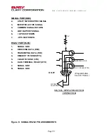
The recommended installation procedure is presented in Table 10 . The Table refers to, which
presents a schematic wiring diagram.
Read through the entire procedure before beginning. If any steps are unclear, do not begin the
installation process – please contact Clary Corporation for assistance.
Finish each step completely before continuing to the next.
Table 10: INSTALLATION PROCEDURE FOR TRAFFIC UPS
1. Mount Power Interface Module (PIM) in
Vertical Position
. The PIM mounting bracket can be
removed and repositioned in a number of different directions to accommodate most
applications. The PIM may be mounted near the bottom of the cabinet perpendicular to the
sidewall.
IMPORTANT! PIM MUST BE MOUNTED IN A
VERTICAL
POSITION.
2. Disconnect utility input from input terminal block (cabinet side) and connect to Out H terminal
of PIM.
3. Connect Common N terminal of PIM to neutral bus using AWG #8 wire.
4. Connect Common G terminal of PIM to ground bus using AWG #8 wire.
5. Connect Flash connections in the PIM.
a. If immediate Flash on battery is desired, connect to “On Batt” terminals. (“FLASH” for
PIM 60)
b. If delayed Flash on battery is desired, connect to either “Timer” or “Low-Batt”,
depending on installation needs. (Only on PIM 30)
c. Use either NO or NC contacts as required.
d. “Timer” and “Low-Batt” connections can be paralleled if desired to produce Flash if
either condition is present. (Only on PIM 30)
6. Connect utility input cabinet side to input H of PIM.
7. Mount UPS in cabinet.
8. Mount batteries and connect interconnect cables.
9. Connect PIM to UPS:
a. Power cable (circular connector and cable)
b. Signal port (db9 style connector and cable) (Only on PIM 30)
10. Connect batteries to UPS. Make sure eight batteries are wired in series (+ to -) with 96VDC
full potential across complete string.
11.
Test installation for proper operation.
12.
Document installation.

