21
3
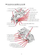
, Disassembly
・
Assembly
(
Frame Assy
)
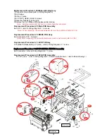
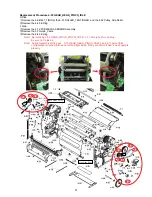
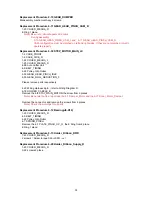
Replacement Procedure DAMPER
①
3-15 Gear_open
Note
)
The Gear_open is not fixed. Please note the drop and the loss.
②
3-1 2 screws
③
3-6 Pull the 3-5 Straight Pin out of the 3-6 Shaft
Note) Lubricate the metal contact parts of 3-6 Shaft
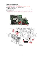
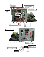
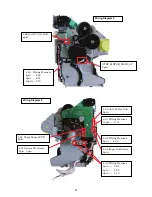
Replacement Procedure 3-38 Inter Lock SW Assy
1 connector
(
refer to the figure below
)
Note
)
Inter Lock Sw if fixed with the hook.
When removing, be careful not to damage the hook.
Replacement Procedure
3-40
Fan Motor
1 connector
(
refer to the figure below
)
2 screws (Screw torque 0.74
±
0.05N
・
m)
Note
)
Take note of the fan direction. Affix it so it blows into the printer.
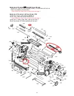
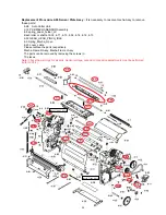
Replacement Procedure 3-32 Power Supply Unit
2 connectors
3-39, 3-334 screws
3-31 Rocking Card Spacer 2 places.
Note) When replacing, the various adjustments must be performed. (refer to Ch.4)
When exchange Power Supply Unit
Even after the power is turned OFF, there are high voltage parts inside. Do not
disassemble for 10 minutes after the power is turned OFF.
Caution
S S
S
S
S
Wiring Diagram 4
3-33
3-40
3-38

