25
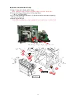
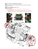
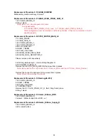
Replacement Procedure 4-53 GEAR_HEAD_PINCH_IDLE
R Side
①
Remove the 4-9 BELT_TIMING, the 4-51 ROLLER_TENTIONER, and the 4-22 Pulley, Grip Roller.
②
Remove the 4-45 E Ring
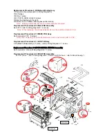
L Side
①
Remove the 2-12 PCB MECHA SENSOR Assembly.
②
Remove the 5-7 Guide_Cable.
③
Remove the 4-45 E Ring.
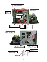
Note
)
By removing 4-53
GEAR_HEAD_PINCH_IDLE
,
4-10 Straight Pin
can drop.
Be sure not to lose it.
Note
)
During Assembly of the gear.
5-15 GEAR_HEAD_PINCH_CAM_L and 6-11 parts CAM
configuration must be matched on left and right sides. If they are not matched, it won't operate
properly.
L
Mecha Flame L Assy
Mecha Flame R Assy
L


