background image


1-28

Cisco RF Gateway 10 Hardware Installation Guide

OL-16264-04

Chapter 1      Overview

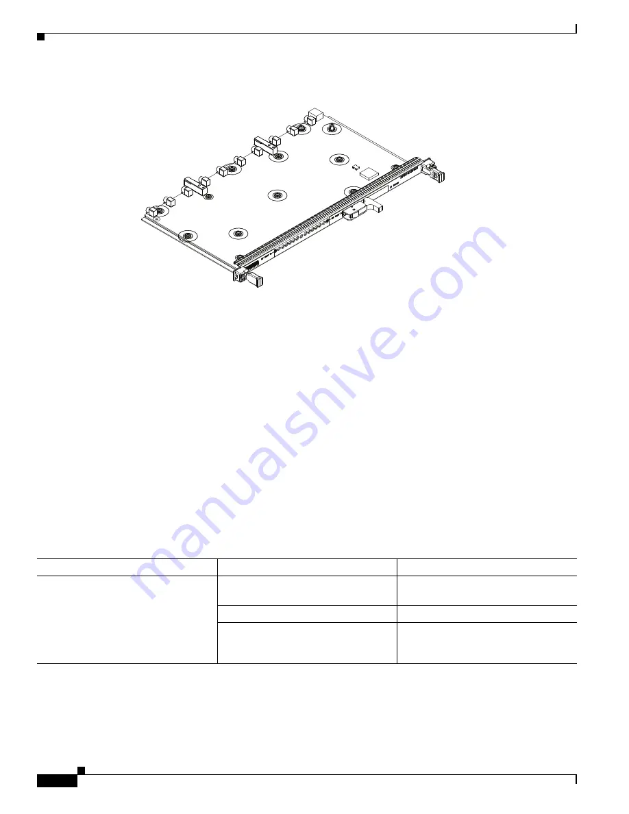
Cisco RFGW-10 Components

Figure 1-16

RF Switch Card

The RF Switch Card supports the following features:

10 RF bi-directional RF ports per RF Switch card

System support for 12 RF Switch cards, 120 RF Ports per chassis

Wire once interface: Coax cables are independent of the RF card insertion and removal

OIR (Hot Swap) and field upgradeability

Supports SW field upgrades

Exceeds DOCSIS DRFI compliance requirements over 5 MHz to 1.2 GHz frequency range

No active gain in any switch path

Support for Cisco UCH2 Dense (MCX) connector

Upto two flexible redundancy groups, each capable of N:1

LED to indicate RF Switch’s active or fail mode

CLI support for configuring and monitoring the status information

Table 1-13

Status LEDs

273442

LED

Color/Status

Description

POWER

Blank

RF Switch is not powered or Severe 
firmware corruption

Green

Normal operating conditions

Blinking Green

Severe error condition (possibly power 
out of specification or firmware 
corruption)

Содержание RFGW-10

Страница 1: ...e Installation Guide July 25 2012 THE SPECIFICATIONS AND INFORMATION REGARDING THE PRODUCTS IN THIS MANUAL ARE SUBJECT TO CHANGE WITHOUT NOTICE ALL STATEMENTS INFORMATION AND RECOMMENDATIONS IN THIS MANUAL ARE BELIEVED TO BE ACCURATE BUT ARE PRESENTED WITHOUT WARRANTY OF ANY KIND EXPRESS OR IMPLIED USERS MUST TAKE FULL RESPONSIBILITY FOR THEIR APPLICATION OF ANY PRODUCTS Text Part Number OL 16264 ...

Страница 2: ...PRACTICE IN NO EVENT SHALL CISCO OR ITS SUPPLIERS BE LIABLE FOR ANY INDIRECT SPECIAL CONSEQUENTIAL OR INCIDENTAL DAMAGES INCLUDING WITHOUT LIMITATION LOST PROFITS OR LOSS OR DAMAGE TO DATA ARISING OUT OF THE USE OR INABILITY TO USE THIS MANUAL EVEN IF CISCO OR ITS SUPPLIERS HAVE BEEN ADVISED OF THE POSSIBILITY OF SUCH DAMAGES Cisco and the Cisco logo are trademarks or registered trademarks of Cisc...

Страница 3: ...ngine V 10GE 1 15 Supervisor Engine Components 1 16 Supervisor Engine LEDs 1 16 Ethernet Management Port 1 16 Supervisor Memory 1 17 Cisco RFGW 10 Supervisor Engine 7 E 1 17 Features of the Cisco RFGW 10 Supervisor Engine 7 E 1 18 Front Panel LED 1 19 Physical and Environmental Specifications 1 20 Cisco RFGW 10 DS 48 Line Card 1 20 DS 48 Line Card Components 1 21 Cisco RFGW 10 DS 384 Line Card 1 2...

Страница 4: ... 11 Interference Considerations 2 11 Rack Mounting and Location Guidelines 2 12 Precautions for Rack Mounting 2 12 Rack Selection Guidelines 2 13 Equipment Rack Guidelines 2 13 Site Planning Checklist 2 14 Preventing Electrostatic Discharge Damage 2 15 Electrical Safety 2 15 Receiving a Cisco RFGW 10 UEQAM 2 17 Chassis Lifting Guidelines 2 17 Tools and Equipment 2 19 Unpacking and Verifying Shippi...

Страница 5: ...Power to Cisco RFGW 10 UEQAM 3 22 Powering On the Cisco RFGW 10 UEQAM 3 28 Connecting System Cables 3 28 Connecting the Lineage Power Shelf to the Cisco RFGW 10 3 28 Cabling the Power Shelf 3 29 Prerequisites 3 29 Required Tools and Equipment 3 29 Steps 3 29 Connecting a Single Power Shelf 3 30 Required Tools and Equipment 3 30 Steps 3 31 Connecting Dual Power Shelves 3 32 Required Tools and Equip...

Страница 6: ...ng the TCC Card 5 22 Installation and Removal of the Line Cards 5 23 Installing the DS 48 Line Card 5 23 Verifying the Status of the DS 48 Line Card 5 26 Removing the DS 48 Line Card 5 26 Installation and Removal of the SFP Modules 5 27 Installing SFP Modules 5 27 Mylar Tab SFP Modules 5 28 Actuator Button SFP Modules 5 29 Bale Clasp SFP Modules 5 31 C H A P T E R 6 Cabling the Cisco RFGW 10 UEQAM...

Страница 7: ...igabit Ethernet X2 Transceiver 6 22 Removing the 10 Gigabit Ethernet X2 Transceiver 6 24 X2 Transceiver Maintenance Guidelines 6 24 SFP Guidelines 6 25 Fiber Optic SFP Modules 6 25 1000BASE T SFP Modules 6 27 CWDM SFP Modules 6 27 Cleaning the Fiber Optic Connectors 6 28 Cabling the TCC Card 6 29 Preventing Electrostatic Discharge Damage 6 29 TCC Card LED Summary 6 30 DTI Physical Connector 6 30 C...

Страница 8: ...R E V I E W D R A F T C I S C O C O N F I D E N T I A L Contents viii Book Title OL 16264 04 ...

Страница 9: ...age 4 Obtaining Documentation and Submitting a Service Request page 5 Document Revision History The Document Revision History table below records technical changes to this document Document Version Date Change Summary OL 16264 01 January 2009 This is the first version of this document OL 16264 02 April 2009 Updated with the new cable assembly information OL 16264 03 June 2012 Updated with informat...

Страница 10: ...his guide require a certified electrician Document Organization The major sections of this installation guide are Section Description Chapter 1 Overview This chapter provides an overview of the Cisco RFGW 10 UEQAM Chapter 2 Preparing Your Site for Installation This chapter provides site preparation guidelines for installing the Cisco RFGW 10 UEQAM Chapter 3 Cisco RFGW 10 UEQAM Installation This ch...

Страница 11: ...and keywords and user entered text appear in bold font italic font Document titles new or emphasized terms and arguments for which you supply values are in italic font Elements in square brackets are optional x y z Required alternative keywords are grouped in braces and separated by vertical bars x y z Optional alternative keywords are grouped in brackets and separated by vertical bars string A no...

Страница 12: ...ure Amplitude Modulation UEQAM and the Cisco IOS software running on it contain extensive features and functionality which are documented in the following resources All documentation related to the Cisco RF Gateway 10 is listed in the online Cisco RF Gateway 10 Documentation Roadmap The Cisco RF Gateway 10 Quick Start Guide contains installation and configuration information It contains quick refe...

Страница 13: ...nthly What s New in Cisco Product Documentation which also lists all new and revised Cisco technical documentation at http www cisco com en US docs general whatsnew whatsnew html Subscribe to the What s New in Cisco Product Documentation as a Really Simple Syndication RSS feed and set content to be delivered directly to your desktop using a reader application The RSS feeds are a free service and C...

Страница 14: ...6 Cisco RF Gateway 10 Hardware Installation Guide OL 16264 04 ...

Страница 15: ...S solution The Cisco RFGW 10 is a centralized switching architecture leveraged from the Cisco Catalyst 4500 Series switches The Cisco RFGW 10 is a 13 rack unit carrier class modular chassis designed for providing front to back airflow and system level redundancy All chassis components are hot swappable and redundant The chassis supports wire once cabling for RF line cards and an integrated dual zo...

Страница 16: ...ontrol TCC DTI Card Slots 1 1 Redundant 10 Universal Line Card Slots N 1 Redundant 12 RF Switch Card Slots Dual Zone Redundancy 2 DC PEM Slots 1 1 Redundant 1 Fan Tray Module Cisco RFGW 10 Functional Overview The Cisco RFGW 10 is a Carrier Class Universal Edge QAM UEQAM platform that offers concurrent support for Standard and High Definition Digital Broadcast Television Switched Digital Video SDV ...

Страница 17: ... Supervisors RPR SS TCC and DC PEMs support 1 1 redundancy The line card slots can be enabled in either a single N 1 redundancy configuration or a dual redundancy configuration N 1 M 1 RF data path redundancy is enabled by the integrated RF Switch matrix which supports dual redundancy groups The following sections provide a high level overview of the downstream data path 1 Data packets are receive...

Страница 18: ...guration in the onboard flash memory The configuration information read from the flash memory is buffered in the operational memory following initialization and is written to the flash memory device when the configuration is saved Each line card also contains an onboard flash memory that is used to store a boot loader similar in function to that used on the Supervisor card However the line card lo...

Страница 19: ...isco RFGW 10 System Configuration Figure 1 1 shows the location of the front and the rear system components for the Cisco RFGW 10 UEQAM Figure 1 1 Cisco RFGW 10 Chassis Components Front and Rear View 271377 3 1 2 4 5 7 6 1 Universal RF line card slots 5 TCC DTI card slots 2 Supervisor card slots 6 DC PEMs 3 LCD Push button panel 7 RF switch cards coaxial cable termination slots 4 Fan assembly ...

Страница 20: ...witch cards coaxial terminations TCC DTI Clock cards and the power supply modules All components excluding the LCD are hot swappable and field replaceable A fully configured system will operate with a single DC PEM installed the second PEM is required for power supply redundancy and power load sharing Note Proper configuration of the DC power input requires that both Input 1 and Input 2 are connec...

Страница 21: ...heat from the system and control the temperature of the chassis system components except the DC PEM which contains its own internal fan The fan assembly is a multi fan design that pulls ambient air from the lower front of the chassis and exhausts air out of the rear top of the chassis The fan assembly provides individual fan control and failure monitoring multiple thermistors to monitor exhaust ai...

Страница 22: ...n in Figure 1 4 Figure 1 4 Cisco RFGW 10 Airflow The fan tray has four speed levels based on the operating control modes for the system After power on the fan speed is set according to the Supervisor provided ambient average air temperature and the configured speed control mode in the system configuration The default control mode setting configures the fans at maximum speed The speed of the fans r...

Страница 23: ...ceplate Figure 1 6 Cisco RFGW 10 Fan Assembly LED Color Status Description Green System OK System is functioning normally all fans are operating Amber Failure Any Type of Failure A single fan has failed system triggers alarms but the fan assembly is still able to cool the chassis Repair or replace the fan assembly as soon as possible 273443 273444 ...

Страница 24: ... external DC inputs Input 1 and Input 2 must be connected as shown in Figure 1 7 Input 1 and Input 2 are individual power inputs Both power inputs on the PEM must be wired to external power for the Cisco RFGW 10 UEQAM to operate properly If both inputs are not connected to external power the Cisco RFGW 10 UEQAM will not power on DC PEM features Closed frame NEBS compliant module design Front to ba...

Страница 25: ...1 11 Cisco RF Gateway 10 Hardware Installation Guide OL 16264 04 Chapter 1 Overview Cisco RFGW 10 Components Figure 1 7 shows the DC PEM faceplate Figure 1 7 DC PEM Faceplate 273170 ...

Страница 26: ...rectly with reverse polarity Sometimes it also indicates a failure on the power input Blank External power source is not providing power correctly typically no power is provided FAN FAIL Blank Normal Operation Red Alarm Condition Fan operation is not normal Fault Blank Normal Operation Red Alarm Condition System Fault General fault indications Power supply is not operating normally CUR LIM FAIL Bl...

Страница 27: ...for DC input 1 Input Voltage Range 48VDC to 60VDC nominal 40VDC to 60VDC full range Wiring 2 Gauge 4 Gauge Must Use Right Angle Power LUG Input 2 48V Negative DC input from external battery source Input Voltage Range 48VDC to 60VDC nominal 40VDC to 60VDC full range Wiring 2 Gauge 4 Gauge Must use Right Angle Power LUG Input 2 RTN Battery Return for DC input 1 Input Voltage Range 48VDC to 60VDC nom...

Страница 28: ...en scrolling mechanism to provide navigation capabilities The FPD navigation features are not enabled in this release of the system Specifications Requirements Power Input Range Input voltage 48 VDC or 60 VDC nominal range 40 to 60 VDC Recommended DC service Four 60A services nominal 48 VDC or 60 VDC two 60A services per PDU Required Lugs 90 angled industry standard 2 hole compression lugs with ho...

Страница 29: ...the following supervisor engines for the Cisco RFGW 10 Cisco Supervisor Engine V 10GE page 1 15 Cisco RFGW 10 Supervisor Engine 7 E page 1 17 Cisco Supervisor Engine V 10GE Figure 1 9 Supervisor Engine V 10GE for the DS 48 Line Card Note The Cisco Supervisor Engine V 10GE doe not support the Cisco RFGW 10 DS 384 line card LED Color Status Description POWER Blank Power is not on Green Power is on A...

Страница 30: ...LEDs Table 1 7 describes the meaning of the Supervisor Engine LEDs Table 1 7 Supervisor Engine LEDs Ethernet Management Port The supervisor engine has a 10 100 BASE T Ethernet management port The Supervisor engine uses an RJ 45 connector on the front panel with a link status LED LED Status Meaning STATUS Green All diagnostic tests passed Red A test failed Orange System boot or diagnostic test is i...

Страница 31: ...orts are for network management only These ports do not support network switching Supervisor Memory The Cisco RFGW 10 Supervisor provides 512 MB SODIMM SDRAM 64 MB flash memory and 512 KB NVRAM Cisco RFGW 10 Supervisor Engine 7 E Starting with Cisco IOS XE Release 3 2 0SQ the Cisco RFGW 10 supports a new supervisor engine for the Cisco RFGW 10 DS 384 line card Note The Cisco Supervisor Engine 7 E ...

Страница 32: ...he switch Note Use a paper clip or other small pointed object to press the RESET switch ACTIVE SUP LED The active supervisor engine LED indicates whether the supervisor engine is active or in standby mode in redundant supervisor engine configurations See Table 1 9 UTILIZATION LEDs Eight LEDs indicate as an approximate percentage the current traffic load over the backplane SeeTable 1 9 USB connecto...

Страница 33: ...FP transceivers or SFP transceivers Uplink port LEDs Each of the four uplink ports has two LEDs associated with it One LED displays port status when a 1 GB SFP transceiver is installed in the port socket The second LED displays uplink port status when a 10 GB SFP transceiver is installed in the port socket See Table 1 9 Table 1 9 Cisco RFGW 10 Supervisor Engine 7 E Front Panel LEDs LED Color and M...

Страница 34: ...hing orange The power on self test indicates a faulty port Off No signal is detected or there is a link configuration failure Uplink link Indicates the status of the uplink port Green The link is operational Orange The link is disabled by user Flashing orange The power on self test indicates a faulty port Off No signal is detected or there is a link configuration failure Item Specification Dimensi...

Страница 35: ...s and initiate failover events if considered catastrophic QAM upconverter HW failure The line card monitors both the digital and RF data integrity The modules also provide a comprehensive alarm structure to the system CPU which allows constant monitoring of the UPX Environmental alarms temperature voltage frequency Software kernel failures Software module failure DTI Clock Timing failures both int...

Страница 36: ...1 22 Cisco RF Gateway 10 Hardware Installation Guide OL 16264 04 Chapter 1 Overview Cisco RFGW 10 Components Two SFP Gigabit uplink ports ...

Страница 37: ...DTI input information the TCC card generates DOCSIS 10 24 MHz clock and timestamp information to every line card in the chassis All clocks and DOCSIS information are redundant When there is no external DTI clock the TCC provides an internal DOCSIS DTI clock and time stamp reference When two TCC cards are installed they are configured as active and backup redundant If the TCC card in the first slot...

Страница 38: ... card role is transferred to the redundant backup card without loss of data The following is a summary of the TCC card s functions and features Generates and distributes 10 24 MHz clock references and 32 bit timestamp references to every cable interface line card Drives the LCD module used to display the system configuration and status information Proxy control mechanism via supervisor cards for t...

Страница 39: ... 1 ACT Yellow Indicates that the DTI server is connected however the DTI lock and communication is not established Off When DTI ACT is Off and the DTI Link is Green it indicates normal DTI connection When DTI ACT is Off and the DTI LINK is Off it indicates that the DTI interface is not linked with the Server DTI 1 LINK Green Indicates that the DTI Client has established connection with the server ...

Страница 40: ... the DTI server Yellow illumination indicates a positive communication link with the server The lower LED LINK can either be green or off When green it indicates that the DTI client has established connection with the server and the frequency is locked A typical transition of the LEDS is the ACK LED illuminates yellow linked after the system comes up and when the DTI frequency is locked the ACK LE...

Страница 41: ...oviding 120 RF ports for the system Note the chassis MUST include all 12 RF Switch cards for proper operation Each Switch Card supports a single Cisco UCH2 connector header the UCH2 supports 10 MCX coaxial connections per card The RF Switch card is physically separate from the RF line cards slots allowing insertion or removal of the RF line cards without disruption of the cable plant wiring The RF...

Страница 42: ...ility Supports SW field upgrades Exceeds DOCSIS DRFI compliance requirements over 5 MHz to 1 2 GHz frequency range No active gain in any switch path Support for Cisco UCH2 Dense MCX connector Upto two flexible redundancy groups each capable of N 1 LED to indicate RF Switch s active or fail mode CLI support for configuring and monitoring the status information Table 1 13 Status LEDs 273442 LED Colo...

Страница 43: ... rack when viewed from the front This allows the DC output terminals of the external AC input power shelf to be on the same side as the DC input terminals of the Cisco RFGW 10 chassis The Lineage AC DC power shelf has two DC power sources four AC input power supply sources and J1 and J2 Jumper connectors The J1 connector is used to connect a control interface cable and J2 connector is used for a s...

Страница 44: ... the power shelf Each AC power supply module has an individual AC facility cord attachment All four AC input cords must be attached to the facility for all four AC power modules to function The DC interconnect cables provide DC output power to the DC PEM modules on the Cisco RFGW 10 See Figure 1 18 Note The AC input and DC output power cables are supplied along with the Lineage kit It is recommend...

Страница 45: ...th Cables To meet compliance standards use the DC power cables 3 m cable supplied along with the Lineage power shelf while cabling the Lineage AC DC power shelf to the Cisco RFGW 10 For information on connecting the Lineage power shelf see Connecting the Lineage Power Shelf to the Cisco RFGW 10 page 3 28 1 DC output power supply cables 2 AC input power supply cables 334294 1 1 2 2 ...

Страница 46: ...1 32 Cisco RF Gateway 10 Hardware Installation Guide OL 16264 04 Chapter 1 Overview Supported External AC Input Power Shelf ...

Страница 47: ...dy to install it Keep the chassis in the shipping container to prevent accidental damage until you determine an installation site Use the appropriate unpacking documentation included with the system Warning Read the installation instructions before connecting the system to the power source Statement 1004 Warning Only trained and qualified personnel should be allowed to install replace or service t...

Страница 48: ...must also meet the requirements of any other normative documents for example standards technical specifications laws or regulations Review the safety warnings listed in the Regulatory Compliance and Safety Information Guide that accompanied your Cisco RFGW 10 UEQAM before installing configuring or maintaining the router Never attempt to lift an object that might be too heavy for you to lift by you...

Страница 49: ...of LSSGR FR 64 TSGR FR 440 and NEBSFR FR 2063 Telcordia Technologies Generic Requirements GR 1089 CORE Issue 4 June 2006 Caution Wear an ESD protective wrist strap on your wrist and attach the other end to a bare metal grounded surface to prevent ESD Caution To comply with the Telcordia GR 1089 NEBS standard for electromagnetic compatibility and safety for Ethernet RJ 45 ports use only shielded Et...

Страница 50: ...l to metal contact Any paint or other nonconducting coatings shall be removed on the surfaces between the mounting hardware and the enclosure or rack The surfaces shall be cleaned and an antioxidant applied before installation The grounding architecture of this product is DC isolated DC I DC powered products have a nominal operating DC voltage of 48 VDC Minimal steady state DC operating voltage is...

Страница 51: ...isco The use of cables that are certified by Electrical Appliance and Material Safety Law that have PSE shown on the code is not limited to Cisco designated products Statement 371 Warning Only trained and qualified personnel should be allowed to install or replace this equipment Statement 1030 Warning This product relies on the building s installation for short circuit overcurrent protection Ensur...

Страница 52: ...aser products Statement 1055 Warning Invisible laser radiation may be emitted from the end of the unterminated fiber cable or connector Do not view directly with optical instruments Viewing the laser output with certain optical instruments for example eye loupes magnifiers and microscopes within a distance of 100 mm may pose an eye hazard Statement 1056 Warning To prevent personal injury or damage...

Страница 53: ... working with your Cisco RFGW 10 UEQAM system Keep your system components away from radiators and heat sources and do not block cooling vents Do not spill food or liquids on your system components and never operate the product in a wet environment Do not push any objects into the openings of your system components Doing so can cause fire or electric shock by shorting out interior components Positi...

Страница 54: ...proper location Table 2 3 shows the weight and dimensions of the Cisco RFGW 10 UEQAM Table 2 3 Physical Characteristics of Cisco RFGW 10 UEQAM Environmental Characteristic Minimum Maximum Steady State Operating 32 F 0 C 104 F 40 C at 10 000 feet Storage 4 F 20 C 158 F 70 C Humidity operating noncondensing 5 90 Humidity nonoperating noncondensing 5 95 Altitude operating over allowable temperature r...

Страница 55: ...ut power on one line fails In systems configured with the redundant power option connect each of the two DC PEMs to a separate input power source If you fail to do this your system might be susceptible to total power failure due to a fault in the external wiring or a tripped circuit breaker To prevent a loss of input power be sure the total maximum load on each circuit supplying the DC PEM is with...

Страница 56: ...ignaling EMI and connector compatibility Possible cable types are fiber thick or thin coaxial foil twisted pair or unshielded twisted pair cabling Also consider any additional interface equipment you need such as transceivers hubs switches modems channel service units CSU or data service units DSU Before you install the Cisco RFGW 10 UEQAM have all additional external equipment and cables on hand ...

Страница 57: ...owing sections describe sources of interference and how to minimize its effects on the Cisco RFGW 10 UEQAM system Electromagnetic Interference All equipment powered by AC current can propagate electrical energy that can cause electromagnetic interference EMI and possibly affect the operation of other equipment The typical sources of EMI are equipment power cords and power service cables from elect...

Страница 58: ...quate electrical surge suppression and shielding of signal cables in your Cisco RFGW 10 UEQAM operating environment Rack Mounting and Location Guidelines The Cisco RFGW 10 UEQAM is designed for standalone two post 19 inch rack mount four post 19 inch rack mount and closed cabinet systems with front and rear doors The sections that follow describe criteria for selecting a rack to mount the Cisco RF...

Страница 59: ...you plan to install the system in has metric threaded rails you must provide your own metric mounting hardware Perforated top and open bottom for ventilation to prevent overheating Leveling feet for stability Equipment Rack Guidelines The placement of the rack can affect personnel safety system maintenance and the system ability to operate within the environmental characteristics described in Tabl...

Страница 60: ...airflow to keep the system operating within the environmental characteristics and the air temperature is sufficient to compensate for the heat dissipated by the system Avoid locating the Cisco RFGW 10 UEQAM in a location in which the chassis air intake vents could draw in the exhaust air from adjacent equipment Consider how the air flows through the Cisco RFGW 10 UEQAM The Cisco RFGW 10 UEQAM airf...

Страница 61: ...from your body before you touch any of your system components such as an microprocessor As you continue to work on your system periodically touch an unpainted metal surface on the computer chassis Following are guidelines for preventing ESD damage Always use an ESD preventive wrist or ankle strap and ensure that it makes good skin contact Before removing a card from the chassis connect the equipme...

Страница 62: ...es the equipment unsafe Never install equipment that appears damaged Carefully examine your work area for possible hazards such as moist floors ungrounded power extension cables and missing safety grounds In addition use the guidelines that follow when working with any equipment that is disconnected from a power source but is still connected to telephone wiring or other network cabling Never insta...

Страница 63: ...ave at least two people available to help with the installation and ensure safe lifting Chassis Lifting Guidelines The fully configured system weighs approximately 275 pounds The chassis is not intended to be moved frequently Before you install the system ensure that your site is properly prepared so you can avoid moving the chassis later to accommodate power sources and network connections Cautio...

Страница 64: ...nsure that your footing is solid and balance the weight of the chassis between your feet Lift the chassis slowly never move suddenly or twist your body as you lift Keep your back straight and lift with your legs not your back If you must bend down to lift the chassis bend at the knees not at the waist to reduce the strain on your back muscles Note To unpack the Cisco RFGW 10 UEQAM it is recommende...

Страница 65: ...ee ground lugs Heat shrink tubing or electrical insulation for exposed DC power and ground crimp joints 12 universal cable holders UCH2 supplied in the accessory kit does this require a change T 10 TORX driver tool Tape measure optional Level optional MCX terminated cable bundle optional Rack mount kit provided in the accessory kit Ten 4 AWG wire 90 degree dual ring lugs 0 63 spacing for M6 studs ...

Страница 66: ...Cisco RFGW 10 UEQAM shipping container Step 5 Check the contents of the boxes containing accessory items Verify that you have received all equipment listed in your order Step 6 Check that all Cisco RFGW 10 UEQAM components and DC PEM you ordered are installed in the chassis Ensure that the configuration matches the packing list Checking the Shipping Container Contents Use the components list to ch...

Страница 67: ...ur new router Component Description Received Chassis Cisco RFGW 10 UEQAM chassis configured with fan tray 12 RFGW 10 RFSW1 cards two RFGW TCC1 cards dual DC PEM Components Check that the proper number and type of cards are installed for the Supervisor Slots and Universal RF slots All other empty slots should be filled with blank panels Accessories Kit 2 Front chassis rack mount brackets that you w...

Страница 68: ...environmental specifications verified Required passwords IP addresses device names and so on available Required tools available Network connection equipment available Cisco RFGW 10 UEQAM Chassis installed into a rack and all interfaces re installed Rear RF Cable management bracket installed optional but recommended to be installed after rack mounting DC power cable s connected to DC source s and R...

Страница 69: ...nstallation Brackets page 3 6 Installing the Chassis Installation Handles page 3 7 Attaching the Chassis Rack Mount Brackets page 3 9 Installing the Cisco RFGW 10 UEQAM in a Rack page 3 12 Attaching a Chassis Ground Connection page 3 18 Attaching the Cable Management Bracket page 3 20 Connecting Power to Cisco RFGW 10 UEQAM page 3 21 Connecting the Lineage Power Shelf to the Cisco RFGW 10 page 3 2...

Страница 70: ... Installation Guide OL 16264 04 Chapter 3 Cisco RFGW 10 UEQAM Installation Cisco RFGW 10 UEQAM Description Front View Figure 3 1 shows the Cisco RFGW 10 UEQAM with the modules installed Figure 3 1 Cisco RFGW 10 UEQAM Front View 273674 ...

Страница 71: ... Two DC PEMs are accessed from the rear of the router Note You have already unpacked your chassis and read all the site requirements for your new equipment Proceed with the installation Warning Before you install operate or service the system read the Regulatory Compliance and Safety Information for the Cisco RF Gateway 10 publication This document provides important safety information you should ...

Страница 72: ...5 inches or 57 785 cm of vertical rack space Measure the proposed rack location before mounting the chassis in the rack Before using a particular rack check for obstructions such as a power strip that could impair rack mount installation If a power strip does impair a rack mount installation remove the power strip before installing the chassis and then replace it after the chassis is installed All...

Страница 73: ...imensions of the Cisco RFGW 10 UEQAM Rack Mounting a Cisco RFGW 10 UEQAM The Cisco RFGW 10 UEQAM can be installed in either front mount or mid mount configurations The chassis rack mounting flanges must be secured directly to the chassis before lifting it into the rack Verifying Rack Dimensions Before you install the chassis measure the space between the vertical mounting flanges rails on your equ...

Страница 74: ...g steps Step 1 Determine where in the rack you want the chassis to be mounted If you are mounting more than one chassis in the rack then start from the bottom up or the center of the rack Install the chassis installation bracket where the chassis bottom will be positioned vertically in the rack Step 2 Secure the chassis installation bracket to the front rails with the rack mount screws Step 3 If t...

Страница 75: ...ed Installing the Chassis Installation Handles This section explains how to attach the chassis installation handles to the chassis Before installing the chassis in the rack it is recommended that you install a chassis lifting handle to each side of the chassis to aid in lifting the chassis onto the rack Note It is recommended to install the two side chassis installation handles while unpacking to ...

Страница 76: ... handle captive screws See Figure 3 5 Step 2 Install the two chassis installation handles on either side of the chassis and tighten the captive screws Caution Ensure that the captive screws are secured tightly prior to loading the handles to prevent injury or damage to the chassis Figure 3 5 Attaching the Chassis Installation Handles to the Cisco RFGW 10 UEQAM After the chassis rack mount brackets...

Страница 77: ...chassis rack mount brackets and mount the chassis in the rack Chassis Front Rack Mount Brackets Installation To install the front rack mount brackets on a Cisco RFGW 10 UEQAM complete the following steps Step 1 Locate the threaded holes on the front sides of the chassis that align with the holes in the rack mount bracket Ensure that you hold the front rack mount bracket with the ear and holes faci...

Страница 78: ...sis Mid Mounted Rack Mount Bracket Installation If you are rack mounting the chassis using a mid mounted configuration then it provides for the chassis being recessed in the rack or installed in a two post rack Note Chassis installation handles cannot be installed if the chassis is to be mid mounted 1 Front rack mount bracket 3 Front rack mount bracket screws 2 Cisco RFGW 10 UEQAM chassis 273684 1...

Страница 79: ... and towards the rear of the chassis see Figure 3 7 Step 2 Install all the six M5 undercut flat head screws provided in the accessory kit to secure each of the rack mounting bracket to the chassis There will be three screws installed on each end of the rack mounting bracket Step 3 Repeat Step 1 through Step 2 on the other side of the chassis Step 4 Install the chassis in the rack To install the Ci...

Страница 80: ... the rack When mounting this unit in a partially filled rack load the rack from the bottom to the top with the heaviest component at the bottom of the rack If the rack is provided with stabilizing devices install the stabilizers before mounting or servicing the unit in the rack Statement 1006 Caution Before you proceed read the instructions in Chassis Lifting Guidelines section on page 2 17 To ins...

Страница 81: ... side chassis installation handles and slide the chassis into position in the rack Note If you have the chassis installation handles installed on the front rack mount rails they can be used to aid in sliding the chassis into the rack Additionally the fan tray handles can be used during the rack installation process Step 6 Position the chassis until the rack mounting flanges flush against the mount...

Страница 82: ...these steps a Insert a bottom screw into the rack mount ear on each side and use a hand held screwdriver to tighten the screw to the rack rail Tip In the next step insert the top screw diagonally from the bottom screw that you just attached This helps in keeping the chassis in place b Insert a top screw into each side rack mount bracket and tighten the screw to the rack rail c Insert a minimum of ...

Страница 83: ...u must first remove the handles to install the fourth screw Step 8 Ensure that all screws on each side rack mount brackets are tightened to the equipment rack then the chassis installation brackets can be removed from the rack see Figure 3 10 Figure 3 10 Securing the Side Rack Mount Brackets You can install your Cisco RFGW 10 chassis in a two post rack see Two Post Rack Installation Mid Mounted se...

Страница 84: ...ed or that the rack is otherwise stabilized See the section on the types of racks you can use to install the chassis Step 3 Optional Install the chassis installation bracket into the rack to help support the chassis during installation see Figure 3 11 If you use the bracket this will help support the chassis while you secure it to the rack Figure 3 11 Chassis Installation Bracket Step 4 With two p...

Страница 85: ... helps to keep the chassis in place b Insert a top screw into each side rack mount bracket and tighten the screw to the rack rail c Insert a minimum of four screws per bracket on both sides of the chassis Figure 3 12 Installing the Cisco RFGW 10 in a Two Post Equipment Rack Step 7 Ensure that all the screws on each side of the rack mount brackets are tightened to the equipment rack before the chas...

Страница 86: ...chassis Phillips screwdriver 90 degree 6 AWG wire dual lug chassis ground component provided in the accessory kit 6 AWG grounding wire Have the recommended tools and supplies before you begin this procedure Figure 3 13 shows the Chassis NEBS grounding attached to the chassis in the lower left corner of the rear of the chassis Figure 3 13 Installing the Cisco RFGW 10 UEQAM Telcordia Ground Connecti...

Страница 87: ...to be removed or disconnected Use the following procedure to attach the grounding lug to the chassis ground connector on your chassis Step 1 Use the wire stripper to strip one end of the AWG 6 wire approximately 0 75 inches 19 05 mm Step 2 Insert the AWG 6 wire into the wire receptacle on the 90 degree grounding lug see Figure 3 14 Step 3 Use the crimping tool to carefully crimp the wire receptacl...

Страница 88: ... to coaxial cables exiting the RF switch modules This bracket allows reference configuration that allows installation and removal of cables and modules in the rear of the chassis The RF cable management bracket for the Cisco RFGW 10 UEQAM contains 12 independent cable management U type features with three captive screws for attaching to the chassis and provides cable dressing of each RF switch car...

Страница 89: ...n to 5 in lbs torque maximum Figure 3 17 shows the cable management brackets attached to the chassis Figure 3 17 Installing the Cable Management Bracket Connecting Power to Cisco RFGW 10 UEQAM Warning The covers are an integral part of the safety design of the product Do not operate the unit without the covers installed Statement 1077 1 Chassis rear left side panel 3 Cable management bracket 2 Cab...

Страница 90: ...ed instructions for removing and replacing the Cisco RFGW 10 DC PEM are in Installation and Removal of the DC PEM section on page 5 2 Caution Always turn off the breaker on the DC PEM unscrew the captive screws and partially remove the DC PEM from the chassis prior to disconnecting connecting the DC power feed cables Connecting DC Input Power to Cisco RFGW 10 UEQAM This section describes how to co...

Страница 91: ...e tongue reference Panduit LCD4 14AF L They must be able to fit over M6 terminal studs at 0 625 inch 15 88 mm centers Note The DC input power cables must be connected to the PDU terminal studs in the proper positive and negative polarity In some cases the DC cable leads are labeled which is a relatively safe indication of the polarity However you must verify the polarity by measuring the voltage b...

Страница 92: ...DC cable lugs ensure proper insulation of the entire 90 degree portion of the lugs where the wire is crimped to avoid hazardous conditions and where the DC input power is accessible through the terminal cover of the DC PEM with shrink tubing Note Detailed instructions for removing and replacing the Cisco RFGW 10 UEQAM DC PEM are in Installation and Removal of the DC PEM section on page 5 2 To conn...

Страница 93: ...ch must be connected first and follow these steps a Using the provided grounding lug in the accessory kit replace the washers and Kepnut screw in the following order Washer Grounding cable lug Kepnut screw b Tighten the Kepnut screws on the power supply studs to the recommended torque of 18 in lbs minimum to 22 in lbs maximum Figure 3 19 Cisco RFGW 10 DC PEM 1 DC PEM captive screws 5 Fan 2 DC PEM ...

Страница 94: ...t any contact with metal lead on the ground wire and the plastic cover Step 6 You must wrap the positive and the negative lead cables with the sleeves Take each lead wire and cover the area from the lug to the wire with heavy shrink sleeve Step 7 Insert the negative lead cable first Replace the ground lug with cable in the following order a Washer b Ground lug with negative wire c Kepnut screw Ste...

Страница 95: ...eps 6 through 10 for the second DC input feed to the PEM Note Both DC inputs to the DC PEM must be connected and energized for the RFGW 10 system to operate properly Step 12 Fully install the DC PEM into the power supply bay and tighten the captive fasteners on the faceplate to the chassis Note Tighten the DC PEM captive fasteners to 12 16 in lb torque 1 Plastic cover 3 Negative lead 2 Terminal bl...

Страница 96: ...power command For more information on the commands refer to the command reference publication for your chassis and software Connecting System Cables Keep the following guidelines in mind when connecting external cables to the Cisco RFGW 10 UEQAM To reduce the chance of interference avoid crossing high power lines with any interface cables Verify all cabling limitations particularly distance before...

Страница 97: ...re that power is removed from the DC circuit Statement 1003 Caution Do not connect the AC power cables to the facility power source until the DC power cables are connected to the power shelf and to the Cisco RFGW 10 UEQAM To attach the cables to Lineage power shelf Step 1 Open the safety covers from above the DC terminal blocks by pushing the safety cover up and off the DC power terminal blocks on...

Страница 98: ...bles to the facility wall socket to energize the power shelf Caution Exercise caution while connecting the AC power cables to the an energized wall socket because the power shelf will start supplying power to the Cisco RFGW 10 Connecting a Single Power Shelf Required Tools and Equipment DC PEM module RFGW 10 PWR DC1 One Lineage AC DC power shelf Four Y power cables Amphenol provided in the Lineage...

Страница 99: ...ge power shelf see the Cabling the Power Shelf section on page 3 29 Step 2 Connect the DC power cables to the DC input terminals on the Cisco RFGW 10 UEQAM For information on connecting the DC power cables to the Cisco RFGW 10 see the Connecting DC Input Power to Cisco RFGW 10 UEQAM section on page 3 22 Step 3 Connect the AC power cables to a standard wall socket facility power source to provide p...

Страница 100: ... AC power cables to the facility power sources until the DC power cables are connected to the power shelf and to the Cisco RFGW 10 Step 1 Connect the cables to the two Lineage power shelves see Cabling the Power Shelf section on page 3 29 Step 2 Connect the DC straight power cables to the DC input terminals on the on the Cisco RFGW 10 UEQAM For information on connecting the cables see Cabling the ...

Страница 101: ... shelf 1 6 Red straight cables from Lineage shelf 2 to 48 V terminal on DC PEM modules 2 Lineage power shelf 2 7 Cisco RFGW 10 DC PEM 1 3 Black straight cables from Lineage shelf 1 to RTN terminal on DC PEM modules 8 Earth ground cables 4 Red straight cables from Lineage shelf 1 to 48 V terminal on DC PEM modules 9 Cisco RFGW 10 DC PEM 0 5 Black straight cables from Lineage shelf 2 to RTN terminal...

Страница 102: ...ct cables from the Lineage power shelf and the Cisco RFGW 10 Step 1 Power off the power shelf by disconnecting the power supply at the facility Wait a few minutes before disconnecting the power cables so that they discharge Step 2 Disconnect the AC cables from the standard wall socket Disconnect the AC power cables from each of the AC input power supply sources on the power shelf Step 3 Disconnect...

Страница 103: ...nmental Limits Blank Panels Warning Blank faceplates and cover panels serve three important functions they prevent exposure to hazardous voltages and currents inside the chassis they contain electromagnetic interference EMI that might disrupt other equipment and they direct the flow of cooling air through the chassis Do not operate the system unless all cards faceplates front covers and rear cover...

Страница 104: ...W 10 UEQAM has a single fan tray module which cools the Supervisor Cards Universal RF slots TCC cards and the fan tray as well The Cisco RFGW 10 UEQAM supports hot swapping which lets you install remove and replace without powering off the system Removal and replacement of the fan tray must be coordinated so that the time to remove and replace the fan tray does not exceed 1 5 minutes Note If the r...

Страница 105: ...peed control system for optimized system cooling acoustics and system thermal alarms The Supervisors have thermal sensors located at various locations on the printed circuit board PCB These sensors monitor board level temperatures only Temperatures read from these sensors are used for Supervisor board level thermal alarming and board thermal protection shutdown Note The temperatures read from the ...

Страница 106: ...4 4 Cisco RF Gateway 10 Hardware Installation Guide OL 16264 04 Chapter 4 Thermal Management Environmental Monitoring ...

Страница 107: ...r Cards page 5 9 Installation and Removal of the RF Switch Card page 5 14 Installation and Removal of the TCC Cards page 5 19 Installation and Removal of the Line Cards page 5 23 Installation and Removal of the SFP Modules page 5 27 Warning Read the installation instructions before connecting the system to the power source Statement 1004 Warning Only trained and qualified personnel should be allow...

Страница 108: ...ic interference EMI requirements the DC power supply should be removed from the chassis if the PEM has failed or the circuit breaker is off This section describes how to remove and install the DC PEM see Figure 5 1 for the Cisco RFGW 10 UEQAM Warning Hazardous voltage or energy is present on the backplane when the system is operating Use caution when servicing Statement 1034 Note The DC PEMs are h...

Страница 109: ...ade type with upturned lugs These terminations should be the appropriate size for the wires and should clamp both the insulation and conductor Statement 1002 To install a DC PEM connect it to a power source and verify its operation do the following Before proceeding read the following instructions The color coding of the DC input power supply leads depends on the color coding of the DC power sourc...

Страница 110: ...itions and where the DC input power is accessible through the terminal cover of the DC PEM with shrink tubing Caution Failure to follow this procedure in the right sequence could pose a safety risk and cause damage to the unit Note To avoid hazardous conditions all components in the area where DC input power is accessible must be properly insulated Therefore before installing the DC cable lugs be ...

Страница 111: ...c Kepnut screw Step 10 Tighten the Kepnut screw to the recommended torque of 18 in lbs minimum to 22 in lbs maximum Step 11 Repeat Step 7 and Step 8 for the RTN lead cable Note Secure the wires coming in from the terminal block so that they are not disturbed by casual contact Step 12 Replace and rotate the terminal block plastic cover back into position until it is locked Note Both DC inputs to th...

Страница 112: ... power supply to the chassis is turned off Step 3 Verify that power is off to the DC circuit on the power supply you are removing Note To meet the electromagnetic interference EMI requirements the DC power supply should be removed from the chassis if the PEM has failed or the circuit breaker is off Step 4 Unscrew the top left hand side captive fastener on the power supply faceplate thumb screw fir...

Страница 113: ...s they contain electromagnetic interference EMI that might disrupt other equipment and they direct the flow of cooling air through the chassis Do not operate the system unless all cards faceplates front covers and rear covers are in place Statement 1029 Installation and Removal of the Fan Assembly This section describes how to install and remove the fan assembly of the Cisco RFGW 10 chassis Note A...

Страница 114: ...lane connector Slide it out of the chassis and place it in a safe place Do not touch the fans hold the fan tray by the handles only Installing the Fan Assembly Follow these steps to install the new fan assembly Caution Follow all installation instructions carefully to prevent damage to the connectors Caution Never operate the system for more than three minutes when the fan assembly is removed An o...

Страница 115: ... you should immediately hear them operating If you do not hear them ensure that the fan assembly is inserted completely in the chassis and that the faceplate is flush with the chassis back panel Note The fan tray has multiple speeds based on the ambient air temperature conditions The default control mode setting configures the fans at a maximum speed at startup After startup it may take up to 30 s...

Страница 116: ...the carrier edges only To install a Supervisor Card in a Cisco RFGW 10 UEQAM chassis do the following Step 1 Take necessary precautions to prevent ESD damage as described in the Preparing Your Site for Installation chapter Step 2 Ensure that you have enough clearance to accommodate any interface equipment that you will connect directly to the Supervisor Card ports Step 3 Loosen the captive install...

Страница 117: ...Locations In the Cisco RFGW 10 Chassis Step 5 To install a Supervisor Card turn the module sideways with the board facing right grasp the switching module front panel with one hand and place your other hand under the board s side edge to support the Supervisor Card as shown in Figure 5 4 Do not touch the printed circuit boards or the connector pins 1 Two supervisor slots 273851 1 ...

Страница 118: ...printed circuit board PCB edge and not on the sheet metal carrier edge Step 7 Pivot the two module ejector levers out and away from the faceplate Step 8 Carefully slide the Supervisor Card into the slot until the notches on both the ejector levers engage the chassis top and bottom Step 9 Using the thumb and the forefinger of each hand simultaneously pivot in both the ejector levers to fully seat t...

Страница 119: ...rd Note If you are removing a Supervisor card from the chassis when the system is up and running ensure that the card is in the standby mode If the card is in active mode execute the redundancy force switchover command to change the card to the Standby mode and then remove the card from the chassis Caution When no fiber cable is connected the aperture of the port may be emitting invisible radiatio...

Страница 120: ...tatic mat or antistatic foam or immediately install it in another slot Warning Blank faceplates and cover panels serve three important functions they prevent exposure to hazardous voltages and currents inside the chassis they contain electromagnetic interference EMI that might disrupt other equipment and they direct the flow of cooling air through the chassis Do not operate the system unless all c...

Страница 121: ...igure 5 6 12 RF Switch Cards Installed with UCH2 Note When you handle the RF switch cards use a wrist strap or other grounding device to prevent ESD damage Installing the RF Switch Card The Cisco RFGW 10 UEQAM chassis has horizontal RF switch card slots that are numbered from top to bottom Slots 1 through 12 Caution During this procedure wear grounding wrist straps to avoid ESD damage to the card ...

Страница 122: ...ot and slot card guides See Figure 5 7 Figure 5 7 RF Switch Card Installation Step 5 Gently insert the RF switch card into the open slot while ensuring not to angle the card which could create an interference with the cables or adjacent cards Step 6 Gently push the RF switch card front panel and the side captive screw pull tabs to fully insert and connect the midplane connectors Note While pushing...

Страница 123: ...to re settle the connectors Step 10 Use the flathead screwdriver to tighten the lead screw Turn the lead screw clockwise until it no longer turns 10 in lbs maximum torque 15 in lbs Caution Torquing the lead screw to more than a maximum of 20 in lbs can cause the lead screw to fail Note For a UCH2 as you turn the lead screw clockwise the outer shroud on the UCH moves to cover the red line on the le...

Страница 124: ...ep 1 Take necessary precautions to prevent ESD damage as described in the Preparing Your Site for Installation chapter Step 2 Ensure that you have enough clearance to accommodate any interface equipment that you will connect directly to the RF switch card RF ports Step 3 Carefully move the cables away from the RF switch card slot to reach the lead screw on the UCH Step 4 Use the flathead screwdriv...

Страница 125: ... the sheet metal carrier to guide it Step 12 Place the RF switch card on an antistatic mat or antistatic foam Note If you are returning a card to the factory after removing the card from the chassis immediately place it into an antistatic shielding bag Installation and Removal of the TCC Cards This section describes how to install and remove the TCC cards in a Cisco RFGW 10 UEQAM chassis Note When...

Страница 126: ...o RFGW 10 UEQAM chassis 1 Two TCC cards 273857 RFGW 10 FAN ASSY FAN OK RF SW 1 RFGW 10 RFSW1 RFGW 10 RFSW1 RFGW 10 RFSW1 RFGW 10 RFSW1 RFGW 10 RFSW1 RFGW 10 RFSW1 RFGW 10 RFSW1 RFGW 10 RFSW1 RFGW 10 RFSW1 RFGW 10 RFSW1 RFGW 10 RFSW1 RFGW 10 RFSW1 POWER POWER POWER POWER POWER POWER POWER POWER POWER POWER POWER POWER POWER STATUS MAINT POWER STATUS MAINT DTI2 DTI2 DTI1 DTI1 ACT LNK ACT LNK ACT LNK...

Страница 127: ...e TCC card into the slot until the notches on both the ejector levers engage the chassis TCC slot s top and bottom Step 9 Using the thumb and the forefinger of each hand simultaneously pivot in both the ejector levers to fully seat the TCC card in the backplane connector Caution Always use the ejector levers when installing or removing a TCC card A TCC card that is partially seated in the backplan...

Страница 128: ...n During this procedure wear grounding wrist straps to avoid ESD damage to the card Do not directly touch the backplane with your hand or any metal tool This could result in an electric shock Caution To prevent ESD damage handle the TCC card by the carrier edges only To remove a TCC card from a Cisco RFGW 10 UEQAM do the following Step 1 Disconnect the network interface cables attached to the port...

Страница 129: ...ess all cards faceplates front covers and rear covers are in place Statement 1029 Step 7 If the slot is to remain empty install a TCC blank panel part number RFGW TCC COVER Installation and Removal of the Line Cards Note For information on installing and removing the Cisco RFGW 10 DS 384 line card see the Cisco RF Gateway 10 Downstream 384 Line Card Hardware Installation Guide This section describ...

Страница 130: ...DS 48 line card whichever is present Step 4 Remove the line card blank panel or the existing DS 48 line card from the appropriate RF capable slot as shown in Figure 5 13 If a blank panel is installed keep it for future use If you are removing an existing DS 48 line card follow the instructions in Removing the DS 48 Line Card section on page 5 26 Figure 5 13 DS 48 Line Cards RF Slots 3 through 12 L...

Страница 131: ... 8 Carefully slide the DS 48 line card into the appropriate slot until the notches on both the ejector levers engage the chassis top and bottom Step 9 Using your thumb and forefinger of each hand to simultaneously pivot in both the ejector levers to fully seat the DS 48 line card in the backplane connectors Caution Always use the ejector levers when installing or removing a DS 48 line card A DS 48...

Страница 132: ...green module operational Step 2 When the DS 48 is online use the show module command to verify that the system acknowledges the new module and that the module s status is good Step 3 If the module is not operational re seat it If the module is still not operational contact your customer service representative Removing the DS 48 Line Card Caution When no fiber cable is connected the aperture of the...

Страница 133: ... slot Note If you are returning a card to the factory after removing the card from the chassis immediately place it in an antistatic shielding bag Warning Blank faceplates and cover panels serve three important functions they prevent exposure to hazardous voltages and currents inside the chassis they contain electromagnetic interference EMI that might disrupt other equipment and they direct the fl...

Страница 134: ...s of your SFP modules The optics will not work correctly when obstructed with dust Figure 5 16 Connecting LC Connectors to the SFP Module The SFP modules have three different types of latching devices used to secure and detach the SFP module from a switching module port The three types of SFP modules are described in the following sections Mylar Tab SFP Modules page 5 28 Actuator Button SFP Module...

Страница 135: ...ull the SFP module out see Figure 5 19 Figure 5 19 Removing a Mylar Tab SFP Module Actuator Button SFP Modules The actuator button SFP module see Figure 5 20 has a button that you must push to remove the SFP module from a switching module port Figure 5 20 Actuator Button SFP Module To insert the actuator button SFP module into a switching module port line up the SFP module with the port and slide ...

Страница 136: ...uator button SFP module from a switching module port perform the following steps Step 1 Gently press the actuator button on the front of the SFP module until it clicks and the latch mechanism activates releasing the SFP module from the port see Figure 5 22 Step 2 Grasp the actuator button between your thumb and index finger and carefully pull the SFP module from the port WS 4448 GB LX 1 3 5 7 2 4 ...

Страница 137: ...le Bale Clasp SFP Modules The bale clasp SFP module see Figure 5 23 has a bale clasp that you use to secure the SFP module in a switching module port Figure 5 23 Bale Clasp SFP Module To insert a bale clasp SFP module into a switching module port perform the following steps WS 4448 GB LX STATUS 1 3 5 7 2 4 6 8 2 4 6 8 78483 WS 4448 GB LX STATUS 1 3 5 7 2 4 6 8 2 4 6 8 Actuator button Actuator butt...

Страница 138: ...ort To remove a bale clasp SFP module from a switching module port perform the following steps Step 1 Open the bale clasp on the SFP module With your index finger press the clasp downward as shown in Figure 5 25 If the bale clasp is obstructed and you cannot use your index finger to open it use a small flat blade screwdriver or other long narrow instrument to open the bale clasp as shown in Figure...

Страница 139: ...Removing FRUs Installation and Removal of the SFP Modules Figure 5 25 Removing a Bale Clasp SFP Module Figure 5 26 Opening a Bale Clasp with a Flat Blade Screwdriver WS 4448 GB LX 1 3 5 7 2 4 6 8 2 4 6 8 WS 4448 GB LX 1 3 5 7 2 4 6 8 2 4 6 8 63072 WS 4448 GB LX 1 3 5 7 2 4 6 8 2 4 6 8 63116 ...

Страница 140: ...5 34 Cisco RF Gateway 10 Hardware Installation Guide OL 16264 04 Chapter 5 Installing and Removing FRUs Installation and Removal of the SFP Modules ...

Страница 141: ... coaxial connections per RF switch card The RF switch card is physically separate from the RF line card slots allowing insertion and removal of the RF line cards without disrupting the cable plant wiring Note Quad shield coaxial cable bundles for the Cisco RFGW 10 RF switch card can be purchased from Cisco with the Universal Cable Holders UCH already connected to the coaxial cable bundles Alternat...

Страница 142: ...nd This cable is 9 84 feet 3 m long and the part number is CAB RFSW520QTIMF2 Figure 1 Cable Bundle with UCH2 Units and F Connectors Figure 2 shows the cable bundle for Cisco RFGW 10 line card to RF switch that has three UCH2 units attached to one end and two RF switch header blocks attached to the other end This cable is 3 2 feet 1 m long and the part number is CAB RFSW520QTIMM2 Figure 2 Cable Bun...

Страница 143: ...This cable is 9 84 feet 3 m long and the part number is CAB RFSW520QTPMF2 Figure 3 Cable Bundle with RF Switch Header Blocks and F Connectors Note Customers purchasing custom length quad shield coaxial cable bundles from third party vendors can purchase spare Universal Cable Holders and spare RF switch header blocks from Cisco Refer to Table 6 1 for the applicable Cisco part numbers 1 RF Switch He...

Страница 144: ...terface uses 75 ohm precision miniature video cable bundled cables terminated to 75 ohm MCX connectors The cables come in bundles of five that will fit into the provided rear RF cable management bracket See Figure 6 5 Note The Cisco RFGW 10 UEQAM coaxial termination must use quad shielded 75 ohm precision miniature video cable Note Other bundle types exist for quad shielded 75 ohm precision miniat...

Страница 145: ... RF input in the upstream Note The cable used with the dense connector UCH must be 75 ohm precision miniature video cable and Cisco specified MCX connectors Part Numbers Table 6 1 lists the part numbers for the Cisco RFGW 10 UEQAM RF Switch cards cable kits cables connectors tubing and tools Table 6 1 Part Numbers 273862 MCX connectors F connectors Description Part Numbers Cisco RFGW 10 RF switch ...

Страница 146: ...card to HFC plant 3 UCH2 units attached to one end and 25 F connectors attached to the other end 9 84 feet 3 m long 2 Cable bundle for RF card to RF switch 3 UCH2 units attached to one end and 2 RF switch header blocks attached to the other end 3 2 feet 1 m long 3 Cable bundle for RF switch to HFC plant 2 RF switch header blocks attached to one end and 25 F connectors attached to the other end 9 8...

Страница 147: ...ocedure requiring access to the chassis interior locate the emergency power off switch for the room you are working in Disconnect all the power and external cables before moving a chassis Do not work alone when potentially hazardous conditions exist Never assume that the power has been disconnected from a circuit Always check before proceeding Do not perform any action that would result in a poten...

Страница 148: ...nection section on page 3 18 Handle components by the carrier edges only avoid touching the card components or any connector pins When removing a module place it on an antistatic surface or in a static shielding bag If the module will be returned to the factory place it in a static shielding bag immediately Avoid contact between the modules and clothing The wrist strap protects the card from ESD v...

Страница 149: ...e UCH on the Faceplate Caution While replacing the UCH be careful not to bend the cables in the holder at right angles Step 3 While holding the UCH and the cables in place on the faceplate use your fingers to tighten the lead screw If the UCH and cables do not set securely in place on the faceplate wiggle the holder to set the connectors Step 4 Use the flathead screwdriver to tighten the lead scre...

Страница 150: ...s so that the coaxial cables can be connected even if only one RF line card is installed in the system Installing or Replacing the Cables in the UCH2 This section describes how to install and replace the UCH2 cables The UCH2 universal cable holders must be used with the Cisco RFGW 10 RF switch line cards The UCH is designed to stabilize the cables and hold them in place Note Do not use heat shrink...

Страница 151: ... TORX driver tool to loosen the lock bar on the side where the cable will be installed See Figure 6 9 Figure 6 9 Using the T 10 TORX Driver Tool to Loosen the UCH2 Lock Bar Step 2 Use a flat head screwdriver as a lever to slide open the lock bar if needed See Figure 6 10 RF Switch Line Card Port Cable Color RF Switch User Defined RFSW Slot 12 Red RFSW Slot 11 White RFSW Slot 10 Blue RFSW Slot 9 Gr...

Страница 152: ...Lock Bar on the UCH2 Step 3 Remove the ESD cap from a cable see Figure 6 11 and Figure 6 12 and place it in the hole in the UCH2 See Figure 6 13 Use Table 6 3 to determine the correct color and location for each colored cable Figure 6 11 Removing an ESD Cap from an MCX Connector Figure 6 12 Removing an ESD Cap from an F Connector Step 4 Insert and wiggle the connector into the hole 155820 155824 1...

Страница 153: ...r close completely and use the T 10 TORX driver tool to tighten the screws clockwise torque 10 in lbs 1 13 Newton meters Nm The locking bar is completely closed when they are interlocked with the metal by the lead screw Note The clamp bar maximum torque is 15 in lbs 1 69 Nm Removing Cables To remove the old cables complete the following steps Step 1 Use the T 10 TORX driver tool to loosen the UCH2...

Страница 154: ...ctors are properly seated in the ports on the faceplate a Verify that no cables are broken at the connector b Verify that the cables are properly secured in the UCH c Verify that all the MCX connectors are protruding the same distance out of the UCH Note Use the MCX to F connector adapter provided in the accessory kit to easily adapt the MCX connection for testing the cables 5 Verify that the lock...

Страница 155: ...until the broken part of the lead screw emerges from the hole Step 5 Use your fingers or needle nose pliers to rotate the lead screw the rest of the way out of the hole Cabling the Supervisor Engine Note For information about Cisco RFGW 10 Supervisor Engine 7 E see Cisco RFGW 10 Supervisor Engine 7 E section on page 1 17 For more information on istalling and removing the SFP and SFP transceiver mo...

Страница 156: ...F cable When two Supervisor Engine V 10GEs are present in a Cisco RFGW 10 UEQAM two SFP uplinks are active on both the primary active and secondary standby supervisor engines by default or four uplinks will be active in a non redundant configuration Ethernet Management Port The supervisor includes an out of band management Ethernet port on the front panel known as fa1 This FastEthernet port on the...

Страница 157: ...Flash Port The compact Flash port accepts a Type 1 compact Flash card You can use it for file transfer tasks such as loading a new software image The Flash card is optional and can be obtained from third party suppliers Port Cabling Specifications This section provides port cabling specifications The length of your networks and the distances between connections depend on the type of signal the sig...

Страница 158: ...ne network voltage TNV circuits LAN ports contain SELV circuits and WAN ports contain TNV circuits Some LAN and WAN ports both use RJ 45 connectors Use caution when connecting cables Statement 1021 Note Always keep caps and plugs on the fiber optic connectors on the cable and the switch when they are not in use Warning Invisible laser radiation may be emitted from disconnected fibers or connectors...

Страница 159: ...age the fiber and cause data errors Figure 6 16 SC Fiber Optic Connector Always insert the network connector completely into the socket A secure connection is especially important when you are establishing a connection between a module and a long distance 1 24 miles or 2 km network or a module and a suspected highly attenuated network If the link LED does not light try removing the network cable p...

Страница 160: ...e connections Contaminated connectors can damage the fiber and cause data errors Figure 6 17 LC Fiber Optic Connector Configuring Your Supervisor Engine For information and commands to configure your Supervisor Engine refer to the 1 1 Supervisor Card Redundancy feature guide Note In Supervisor redundancy mode the Cisco RFGW 10 Supervisor 7 E allows users to use the top two front panel data ports o...

Страница 161: ... transceiver Table 6 6 X2 10 Gigabit Ethernet Transceiver Specifications Warning Class 1 laser product Statement 1008 Warning Do not stare into the beam or view it directly with optical instruments Statement 1011 Warning Use of controls adjustments or performing procedures other than those specified may result in hazardous radiation exposure Statement 1057 The following transceiver media types are...

Страница 162: ...ng a small flat blade screwdriver carefully pry the X2 transceiver port cover off the module faceplate Use the two arrows on the port cover as guides for inserting the screwdriver blade Save the port cover for future use Step 2 Remove the 10 Gigabit Ethernet X2 transceiver from its protective packaging Step 3 Check the label on the 10 Gigabit Ethernet X2 transceiver to verify that the 10 Gigabit E...

Страница 163: ... Always inspect and clean the SC connector end faces just before making any connections Always grasp the SC connector housing to plug or unplug a fiber optic cable Step 5 Remove the dust plugs from the network interface cable SC connectors Save the dust plugs for future use Step 6 Inspect and clean the SC connector s fiber optic end faces Tip For complete information on inspecting and cleaning fib...

Страница 164: ...transceiver optical bores and the fiber optic cable SC connectors Step 2 Grip the sides of the 10 Gigabit Ethernet X2 transceiver sleeve with your thumb and forefinger and pull the sleeve out to release the X2 transceiver from the socket connector See Figure 6 19 Figure 6 19 Removing the 10 Gigabit Ethernet X2 Transceiver Step 3 Slide the 10 Gigabit Ethernet X2 transceiver out of the socket and im...

Страница 165: ...mation This encoding provides a way for Cisco to identify and validate that the SFP module meets the requirements for the device The following SFP media types are supported 1000BASE SX GLC SX MM 1000BASE LX LH GLC LH SM 1000BASE ZX GLC ZX SM 1000BASE T GLC T Cisco 1000BASE LX LH interfaces fully comply with the IEEE 802 3z 1000BASE LX standard However their higher optical quality allows them to re...

Страница 166: ...e at each end of the link 63066 SFP Module Wavelength nanometers Fiber Type Core Size micron Modal Bandwidth MHz km Cable Distance 1000BASE SX 850 MMF 62 5 62 5 50 0 50 0 160 200 400 500 722 feet 220 m 902 feet 275 m 1640 feet 500 m 1804 feet 550 m 1000BASE LX L H 1300 MMF1 SMF 62 5 50 0 50 0 9 10 500 400 500 1804 feet 550 m 1804 feet 550 m 1804 feet 550 m 32 810 feet 10 km 1000BASE ZX 1550 SMF 9 ...

Страница 167: ...l add drop multiplexer OADM or multiplexer demultiplexer plug in modules using single mode fiber optic cables with standard SC connectors Figure 1 23 shows a CWDM SFP with the optical port dust plug removed CWDM SFP Module Yellow Coded CWDM SFP 1550 Shown CWDM SFPs come in eight wavelengths that range from 1470 nm to 1610 nm Color markings on the devices identify the wavelength to which the Gigabi...

Страница 168: ...ction quality depends on two factors the type of connector and the proper cleaning and connection techniques Dirty fiber connectors are a common source of light loss Keep the connectors clean at all times and keep the dust covers installed when the connectors are not in use Before installing any type of cable or connector use a lint free alcohol pad from a cleaning kit to clean the ferrule the pro...

Страница 169: ...cabling the TCC card Preventing Electrostatic Discharge Damage Electrostatic discharge ESD damage which occurs when electronic cards or components are improperly handled can result in complete or intermittent failures The AC input power shelf and its AC power modules contain a printed circuit card fixed in a metal carrier Electromagnetic interference EMI shielding and connectors are integral compo...

Страница 170: ...INK LED illuminates green DTI Physical Connector The DTI interface on the TCC card is compliant with the DOCSIS Timing Interface Specification CM SP DTI I04 061222 DTI It is a DTI client device and provides an RJ 45 female connector for each DTI link These interfaces are redundant and can support separate DTI servers The cables used to connect the TCC card to a DTI server should use standard RJ 45...

Страница 171: ...protect the cards from ESD use an antistatic strap each time you handle the modules or connect cables Following are the guidelines for preventing ESD damage Always use an ESD preventive wrist or ankle strap and ensure that it makes good skin contact Before removing a card from the chassis connect the equipment end of the strap to a bare metal unpainted surface on the chassis or rack mount Ensure t...

Страница 172: ... an SFP transceiver in a port socket Mylar Tab SFP modules Actuator Button SFP modules Bale Clasp SFP modules Determine the type of latch your SFP transceiver uses before proceeding Caution We strongly recommend that you do not install or remove the SFP transceiver module with fiber optic cables attached to it because of the potential damage to the cables the cable connector or the optical interfa...

Страница 173: ...Note Different Cisco devices have different SFP module socket configurations Your Cisco device could have either a latch up or a latch down orientation Ensure that you are installing the SFP transceiver in the correct orientation for your Cisco device For more details refer to the hardware installation instructions that was provided with your Cisco device Step 6 Insert the SFP transceiver into the...

Страница 174: ...e network cable into an RJ 45 connector on a 1000BASE T compatible target device Step 12 Observe the port status LED The LED illuminates green when the SFP transceiver and the target device have an established link The LED illuminates amber while the STP discovers the network topology and searches for loops This process takes about 30 seconds and then the LED illuminates green The LED is off when ...

Страница 175: ...n SFP Transceiver Equipped with a Mylar Tab If the SFP transceiver has an actuator button latch gently press the actuator button on the front of the SFP transceiver until it clicks and the latch mechanism releases the SFP transceiver from the socket connector Grasp the actuator button between your thumb and index finger and carefully pull the SFP transceiver straight from the module slot Figure 6 ...

Страница 176: ...QAM channel to the Asynchronous Serial Interface ASI port to monitor the channel on appropriate test equipment A cable with a male BNC connector not supplied is required to connect to the port labeled ASI MON To connect to the ASI monitor port do the following Step 1 Locate the BNC ASI connection on the line card see Figure 1 12 Step 2 Screw the barrel of the male BNC connector to the port labeled...

Страница 177: ...ort on QAM line card in Slot 3 Router configure terminal Router config interface asi 3 15 Router config if no shut Disable the ASI port on QAM line card in Slot 3 Router configure terminal Router config interface asi 3 15 Router config if shut Monitoring a Specific QAM via the ASI Port To route qam output to the ASI port use the following commands Router configure terminal Router config interface ...

Страница 178: ...llowing command Router config if cable byte gap gap num Where gap num is the number of NULL ASI transport NULL bytes between data bytes This could be 1 2 or 4 The default gap value is 1 Example Router configure terminal Router config interface asi 3 15 Router config if cable byte gap 2 Retrieving ASI Statistics To display interface statistics for the ASI port Router show interface asi slot_num 15 ...

Страница 179: ... System Specifications Model Component Specifications Physical specifications Height 13RU 22 75 in 577 85mm Width 17 30 in 439 4 mm without rack mounts installed 17 48 444mm with rack mounts installed Overall Depth 24 23 in 612 9 mm Weight 275 lb 125 kg with dual DC PEMs and RFGW DS 48 line cards Supervisor Slots 2 in front of chassis Universal RF Card Slots 10 in front of chassis RF Switch Slots ...

Страница 180: ... RF Gateway 10 Hardware Installation Guide OL 16264 04 Chapter 7 Cisco RFGW 10 UEQAM System Specifications Power Requirements Power Requirements Table 7 2 lists the power requirements for the Cisco RFGW 10 UEQAM ...

Страница 181: ...06 Btu hour Airflow Front to back flow with 800 CFM exhaust volume main fan tray DC PEM fans at full flow Operating temperature nominal 32 to 104ºF 0 to 40ºC Operating temperature short term 23 to 122 F 5 to 50 C Operating humidity nominal relative humidity 10 to 85 Operating humidity short term 5 to 90 Storage temperature 40 to 158 F 40 to 70 C Storage relative humidity 5 to 95 Operating altitude...

Страница 182: ...7 4 Cisco RF Gateway 10 Hardware Installation Guide OL 16264 04 Chapter 7 Cisco RFGW 10 UEQAM System Specifications Power Requirements ...

Отзывы: