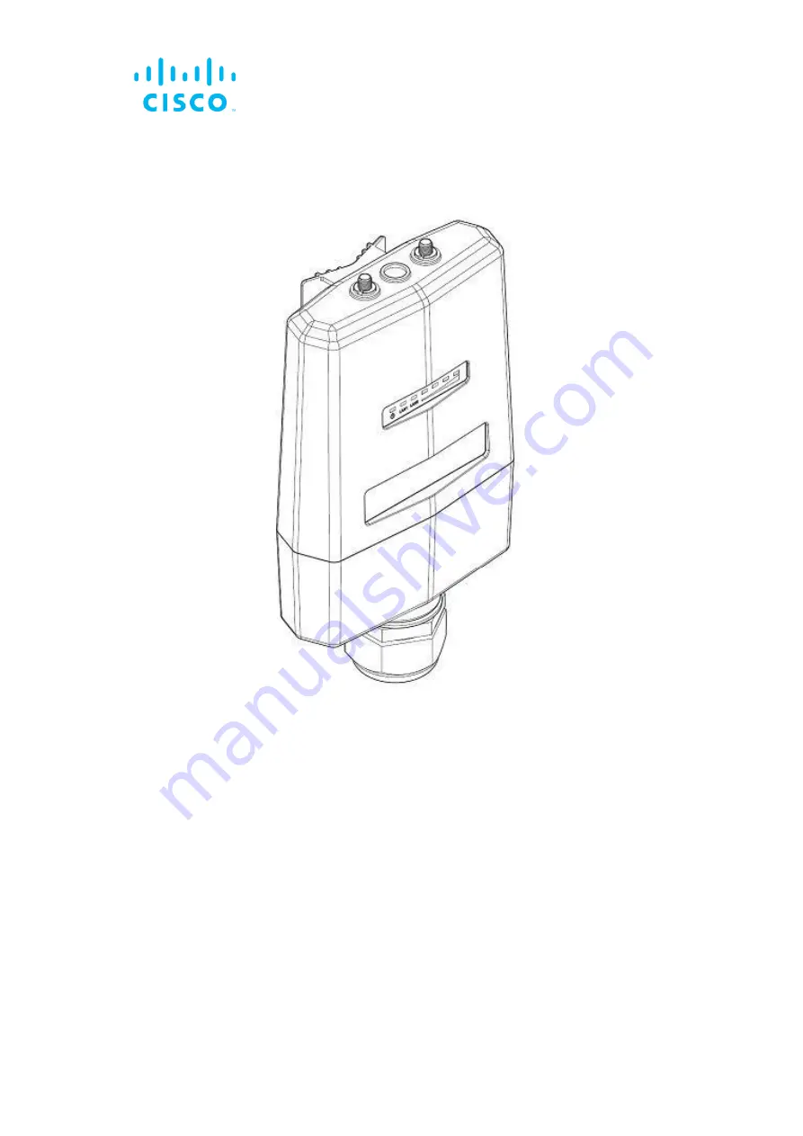
Cisco Ultra-Reliable Wireless
Backhaul FM3500 Endo
Installation and Configuration Manual
(Formerly Fluidmesh)
Model FM3500 | Edition 1.12 | Firmware 9.1.4
Страница 1: ...Cisco Ultra Reliable Wireless Backhaul FM3500 Endo Installation and Configuration Manual Formerly Fluidmesh Model FM3500 Edition 1 12 Firmware 9 1 4 ...
Страница 2: ...r countries To view a list of Cisco trademarks go to this URL www cisco com go trademarks Third party trademarks mentioned are the property of their respective owners The use of the word partner does not imply a partnership relationship between Cisco and any other company 1110R 2018 2020 Cisco Systems Inc All rights reserved ...
Страница 3: ...ddressing 18 3 3 1 Bridge IP Addressing 18 3 3 2 Unit Identification And Addressing 19 Mesh And Bridge Capable Radio Transceiver Identification 19 Operating The Unit In Mesh Point Mode Or Mesh End Mode 20 Network Addressing 21 Fluidmesh Radio Transceivers 21 Connecting And Configuring An Ethernet Edge Device 21 Fluidmesh Radio Transceivers 22 4 Installing The Radio 23 4 1 Installing The Radio Usin...
Страница 4: ...gin For Initial Configuration 49 7 2 2 Initial Configuration With The Unit In Provisioning Mode 52 7 3 Switching Between Offline And Online Modes 58 Uploading A Device Configuration File From FM Racer 59 7 4 Viewing And Accessing The FM Monitor Settings 60 7 5 General Settings 62 7 5 1 The General Mode Window 62 Changing The Operational Mode 63 Changing The Operational Mode On A Mesh Network Capab...
Страница 5: ...luidity Settings 117 Handoff Logic And Rate Adaptation Settings 120 7 7 12 Miscellaneous Settings 121 7 8 Management Settings 123 7 8 1 View Mode Settings 123 7 8 2 Changing The Administrator Username And Password 126 Enabling Remote Access To The Unit By Telnet 127 7 8 3 Overwriting And Upgrading The Unit Firmware 128 7 8 4 Plug In Management 130 7 8 5 The Device Status View 134 The Device Status...
Страница 6: ...M Racer 157 10 Electrical Power Requirements 159 11 Heat Radiation Data 162 12 EC Declaration Of Conformity 164 13 Federal Communications Commission FCC Radio Interference Statement 165 14 Notices And Copyright 168 15 Fluidmesh End User License Agreement 170 15 1 Preamble 170 15 2 Notice 170 15 3 Definitions 170 15 4 License Grant 171 15 5 Uses And Restrictions On Use 171 15 6 Open Source Software...
Страница 7: ...h Organization WHO and other national and global health agencies In May 2019 the FDA stated that there is no link between adverse health effects and exposure at or under the current RF energy exposure limit and that the current FCC RF exposure limits are sufficient to insure the safety of users If any Fluidmesh hardware unit breaks down or malfunctions emits smoke or an unusual smell if water or o...
Страница 8: ...auxiliary mounting kit The FM SHIELD auxiliary mounting kit is a proprietary Fluidmesh solution and is designed specifically to assure the long term durability and reliability of compatible radio transceivers that have been installed in outdoor environments If you need further information regarding the recommended usage of FM SHIELD contact your Fluidmesh Networks representative Relevant technical...
Страница 9: ...distance from the antenna to general bystanders is 20cm 7 9in all FM Ponte kit and x200 radio transceivers or 21cm 8 3 in all FM1300 Otto and x500 radio transceivers Canada This system has been evaluated for RF exposure for humans in accordance with ISED regulation RSS 102 To maintain compliance the minimum separation distance from the antenna to general bystanders is 20cm 7 9in for all Fluidmesh ...
Страница 10: ...rights reserved Page 10 of 177 1 3 Hot surfaces hazard WARNING The outer surfaces of transceiver and gateway unit enclosures may become hot during normal operation During normal operation do not touch or handle the unit enclosure without personal protective equipment ...
Страница 11: ...l rights reserved Page 11 of 177 2 Reporting mistakes and recommending improvements You can help improve this manual If you find any mistakes or if you know of a way to improve the procedures that are given please let us know by E mailing your suggestions to documentation fluidmesh com ...
Страница 12: ...s it is designed to function as an intermediate radio link between a core wired data network and a sub network The unit must be connected to one or more external antennas The unit is designed primarily formobility applications based on Fluidity technology in which specialized antennas need to be deployed for example train to ground automated mining vehicles industrial automation and similar applic...
Страница 13: ...e compatibility Prodigy uses a traffic optimization algorithm that allows every Fluidmesh radio to assign a specific priority level to every forwarded data packet Unit configuration The unit is compatible with Fluidmesh RACER This is a centralized web based interface that allows you to configure monitor and troubleshoot the unit and in certain cases the entire wireless network in real time without...
Страница 14: ...atts 10 to 12 Watts 15 Watts FM 4800 Fiber 13 Watts 15 to 17 Watts 20 Watts Table 2 Power consumption figures gateway units Unit Maximum power consumption realistic system design assumption FM1000 Gateway 60 Watts FM10000 Gateway Gen 1 275 Watts redundant AC power supply 250 Watts non redundant AC power supply FM10000 Gateway Gen 2 300 Watts redundant AC power supply IMPORTANT In service transceiv...
Страница 15: ...sh technologies Prodigy Prodigy is Fluidmesh s proprietary implementation of the Multi Protocol Label Switching MPLS standard Prodigy 2 0 offers greatly improved performance compared to Prodigy 1 0 New features include Fluidity through software plug ins Traffic engineering Advanced Quality of Service QoS Note that Prodigy 2 0 is only compatible with device firmware versions 6 5 and higher IMPORTAN...
Страница 16: ...ss bridge A point to point wireless bridge allows two local networks to communicate with each other A simplified example is shown in Figure 1 page 17 IMPORTANT Prodigy 1 0 and Prodigy 2 0 are not compatible with each other Do not implement the two protocol versions within the same network If you are expanding an existing network using new Fluidmesh hardware components make sure that all components...
Страница 17: ...ridge share the same IP subnet Therefore each network host must use a unique IP address within the subnet 3 2 4 Mesh network architecture Fluidmesh Networks offers wireless networking solutions that are based on the mesh networking architecture but can also fill more traditional networking roles if needed This allows substantial reliability and flexibility advantages when compared to traditional w...
Страница 18: ... Fluidmesh Mesh Networking Architecture 3 3 Fluidmesh network addressing 3 3 1 Bridge IP addressing If needed the Cisco FM3500 Endo can be operated in Bridge mode This creates a single point to point connection between two network segments A simplified example of a Bridge mode connection is shown in Figure 3 page 19 As shipped from the factory the wired ethernet ports of all Fluidmesh hardware com...
Страница 19: ... number is used to identify the physical hardware units within the configurator interface that is used for configuration of the unit A simplified diagram demonstrating the relationship between a wired LAN and a linked mesh radio network containing a mesh end unit and mesh point units is shown in Figure 4 page 20 CAUTION This section contains theoretical explanations of the underlying concepts behi...
Страница 20: ...et to operate in either of two operating modes Mesh Point Mode This is the default operating mode Each radio transceiver unit that is part of the network but is not connected to the wired LAN backbone must be set in Mesh Point mode Mesh End Mode Each radio transceiver unit that is part of the network and is connected to the wired LAN backbone must be set in Mesh End Mode A Mesh End transceiver uni...
Страница 21: ...age 20 In this configuration the private LAN IP address class is 192 168 150 0 with netmask 255 255 255 0 Note that each device has an IP address belonging to this subnet Multiple Fluidmesh radio transceiver units can be connected through a network switch forming radio clusters The proprietary routing protocol will run automatically on the wired part of the network To activate the cluster feature ...
Страница 22: ...erver that resides on the LAN network The Fluidmesh network is totally transparent to DHCP Therefore DHCP requests and responses can be forwarded transparently across the network IMPORTANT If an Ethernet based system using multiple peripheral components is connected to the wireless network assign each peripheral component a fixed IP address If dynamic IP addressing is used the components may not b...
Страница 23: ...taking access to the radio and line of sight into account 2 Place the radio against the utility pole at the chosen mounting point below 3 Route the two tie wraps or metal hose clamps through the clamp holes of the radio s mounting lug below 4 Join the ends of the tie wraps or metal hose clamps Tighten the tie wraps or clamps just enough that the radio can be easily moved in the horizontal plane 5 ...
Страница 24: ...ransceiver unit must be installed To install the included DIN mounting plate on the radio transceiver unit do the following steps 1 Place the transceiver unit on a flat surface so that the unit s mounting lug faces upward 2 Place the included DIN mounting plate over the plate mounting holes below Note that a FM4500 Mobi radio is shown for demonstration 3 Screw the DIN mounting plate to the main bo...
Страница 25: ...FM3500 Endo FM4200 series FM4500 series and FM4800 Fiber transceivers can take advantage of quick release installation if they are installed using the sliding bracket part number FM BRKT SLIDING To mount the unit on a metal backing plate not included you will need the following 4x M3x8 high tensile countersunk screws An appropriately sized metal backing plate drilled and tapped for the mounting ho...
Страница 26: ...f the four holes on the wall using chalk a carpenter s pencil or similar 4 Install the backing plate on the wall using the appropriate method Note the orientation of the mounting holes on the backing plate 5 Using the M3x8 countersunk screws screw the sliding bracket onto the backing plate with the safety catchment portion facing downward below 6 Slide the radio unit downward into the mounting bra...
Страница 27: ...itecture page 17 for details Installation hardware Metal clamps are supplied as part of the installation package to allow mounting of the unit on utility poles Refer to the Cisco FM3500 Endo installation instructions for details Removable bottom housing The unit features a removable water tight bottom housing The bottom housing is equipped with an NPT 1 standard thread cable gland The cable gland ...
Страница 28: ... RJ45 connector is plugged into the correct Ethernet port of the Cisco FM3500 Endo lock the bottom of the RJ45 connector using the side retaining screws When all RJ45 connectors are connected to the unit make sure that the bottom cover of the unit is correctly secured to the unit enclosure 5 1 3 Cisco FM3500 Endo Status and link LEDs Unit and link quality status The front panel of the Cisco FM3500...
Страница 29: ... indicate the following conditions 1 Red Core system boot in progress 2 Yellow Wireless system boot in progress 3 First green Routing engine boot in progress 4 Second green Unit configuration boot in progress If the boot sequence above stops at any LED an error has been detected during that stage of the boot sequence 5 1 4 Supplying power to the Cisco FM3500 Endo TIP During normal operation the re...
Страница 30: ...do radio transceiver unit has two Ethernet ports Figure 7 page 31 IMPORTANT The radio transceiver package does not include a DC IN power source devices capable of accepting DC IN power only a PoE injector or a powered Ethernet switch A suitable power source must be ordered separately For technical data on which power sources are compatible with the Cisco FM3500 Endo refer to Electrical power requi...
Страница 31: ... factory default condition using the procedures in this section CAUTION The unit is designed to take power through 48 Vdc Power over Ethernet only and does not have a dedicated power port Do not attempt to connect any other source of electrical powerto the unit The unit is designed to use an IEEE 802 3at PoE injector Do not connect any PoE injector conforming to IEEE 802 3af to the unit Such injec...
Страница 32: ...he RESET button for one second then release the button immediately The unit will reboot Resetting the unit to factory settings The following methods are available to do a factory reset 1 To do the reset using the offline Configurator interface refer to Resetting the unit to factory defaults page 138 2 To do the reset using FM Racer refer to the Fluidmesh Networks FM Racer User Manual 3 To do the r...
Страница 33: ...rmance operation in outdoor environments and under severe conditions such as water spray salt and extreme fluctuations in cold and heat The Cisco FM3500 Endo has successfully passed stringent environmental certification tests including European Committee for Standardization EN 50155 electronic equipment used on rolling stock for railway applications and EN 45545 fire protection on railway vehicles...
Страница 34: ...ale RJ45 connectors are as shown in the image below With the connector in this orientation the terminals are numbered 1 2 3 4 5 6 7 and 8 from right to left IMPORTANT Always use outdoor rated RF shielded Ethernet cables when connecting the Power and LAN ports of a Fluidmesh hardware device to external hardware IMPORTANT Always use outdoor rated RF shielded Ethernet cables and RF shielded RJ45 male...
Страница 35: ...te tracer Terminal 2 Orange wire Terminal 3 Green wire with white tracer Terminal 4 Blue wire Terminal 5 Blue wire with white tracer Terminal 6 Green wire Terminal 7 Brown wire with white tracer Terminal 8 Brown wire CAUTION RJ45 connectors can be wired according to network cable wiring standards EIA TIA T568A or EIA TIA T568B It is strongly recommended that wiring standard T568A or T568B be chose...
Страница 36: ...J45 plugs comply with the accepted standard for RJ45 LAN PoE connectors Next proceed to the steps in the following table 3 Remove the two screws from the bottom housing 4 Separate the bottom housing from the main body of the unit 5 Route the LAN cables through the hexagon nut then through the rubber seal then through the cable gland nut IMPORTANT The FM3500 Endo is ingress protection rated to stan...
Страница 37: ... unit page 36 7 Place the bottom housing securely against the main body of the radio 9 Re insert and tighten the two screws 10 Check that the cable gland nut is properly tightened If needed re tighten the cable gland nut to the bottom housing 11 Press the rubber seal into the cable gland body Be careful not to crimp or damage the Ethernet cables 12 Install and tighten the hexagon nut ...
Страница 38: ...ave shown outstanding performance We can confidently recommend the following brands Amphenol Huber Suhner Rosenberger Radiall IMPORTANT The FM3500 Endo is ingress protection rated to standards specified by EN 50155 and EN 45545 To ensure the FM3500 Endo remains waterproof and dustproof follow all instructions in this section Following the instructions in this section will also ensure that the FM35...
Страница 39: ...he unit by doing the following steps 1 The number and types of antennas to be connected to the unit will have been decided at the network design stage Verify which antenna will be connected to each RPSMA plug 2 Only remove the rubber sleeve from an RPSMA plug if an antenna must be connected to the plug Next proceed to the steps in the following table ...
Страница 40: ...lide a section of Nylon heat shrinkable tubing over each unconnected antenna cable 5 Push the male RPSMA plug of the antenna cable into the female RPSMA plug of the unit 6 Screw the threaded sleeve of the male plug onto the female plug Tighten the connection by hand only 7 Slide the lengths of Nylon heat shrinkable tubing over the tightened RPSMA connectors 8 Use a heat gun to shrink the tubing on...
Страница 41: ...ake sure a current web browser is installed on your computer For detailed information on which browsers are supported refer to Table 3 page 41 below If needed upgrade your browser version 2 Click this link The Fluidmesh Partner Portal Sign In dialog will be shown 3 Register as a portal user by clicking the Create Account link and following the software prompts Table 3 Supported web browsers Versio...
Страница 42: ...tal login password With 2FA activated you will be asked to provide a secure one time password OTP for each login To set up two factor authentication do the following steps 1 Install an app capable of generating authentication codes on your mobile phone Apps recommended for specific platforms are Google Authenticator or Authy iPhone Android Microsoft Authenticator Windows Mobile 2 Log into the Flui...
Страница 43: ...tion code in the body of the mail Enter the verification code in the Verification code field of the Two Factor Authentication web page The Two Factor Authentication web page will show a QR code 7 Use the authentication app on your mobile phone to scan the QR code on the web page Figure 12 page 43 is a typical example of the QR code you will be shown Figure 12 Two Factor Authentication typical QR c...
Страница 44: ...t is the primary interface with which to configure Fluidmesh radio devices You can operate FM Racer using any internet connected computer with a web browser To access the FM Racer portal do the following steps 1 Log in to the Fluidmesh Partners Portal using your login credentials 2 Click this link For detailed instructions on how to use the FM Racer interface refer to the Fluidmesh Networks RACER ...
Страница 45: ...Cisco and or its affiliates All rights reserved Page 45 of 177 1 Log in to the Fluidmesh Partners Portal using your login credentials 2 Click this link 3 All documents are arranged by category Browse the folders for the documentation you need ...
Страница 46: ...ration CONF file and manual configuration is disabled If devices must be configured on an Offline basis in other words if the device is not connected to the internet and therefore cannot access its configuration settings from the FM Racer Cloud Server a separate configuration file can be uploaded to the device using the Configurator described below The Configurator is a localized configuration sof...
Страница 47: ...802 11 request to send RTS setting Promisc Promiscuous Mode Shows the unit s current setting for backwards compatibility with legacy Fluidmesh units that are no longer in production Noise floor Calibration Shows the unit s current noise floorcalibration setting MAX Transmission MCS Used to choose the modulation and coding scheme by which the unit automatically chooses its maximum data transmission...
Страница 48: ...vice directly to the Fluidmesh device using an Ethernet cable Local access FLUIDITY FREQUENCY SCAN tab Used where mobile Fluidity units are configured with different frequencies SPANNING TREE tab Allows you to build a logical topology for Ethernet networks including backup links to provide fault tolerance if an active link fails QOS tab Contains controls for Quality of Service and Class of Service...
Страница 49: ...isco FM3500 Endo 4 Connect the other end of the Ethernet cable to the Console LAN port on the Cisco FM3500 Endo 5 Manually set the computer s IP address and Netmask to be recognizable by the Cisco FM3500 Endo The correct settings are as follows IP address 192 168 0 10 or any other IP address belonging to subnet 192 168 0 0 255 255 255 0 Netmask 255 255 255 0 6 Launch the computer s web browser 7 E...
Страница 50: ... IMPORTANT Due to rising levels of cyber crime most modern web browsers are built to alert you to possible threats such as hacking spoofing and identity theft Because the Cisco FM3500 Endo is connected to the computer using an unsecured connection in this case a CAT5 6 cable the web browser may show you security warnings like the one above This is normal and expected During the configuration proce...
Страница 51: ...ndow will be shown Figure 15 Fluidmesh device login window 8 The factory set login details are as follows Username admin Password admin 9 Enter the correct username and password Press Enter If your browser shows a time out or similar message the computer may be trying to access the Fluidmesh device through a proxy server To resolve the issue do the following steps 1 Go to Control Panel Internet Op...
Страница 52: ...in window does not appear refer to Changing the Administrator username and password page 126 7 2 2 Initial configuration with the unit in Provisioning Mode The Cisco FM3500 Endo cannot be operated without entering some basic configuration settings These settings allow the unit to connect to a local network and communicate with the network hardware If a new unit is being configured for use for the ...
Страница 53: ...he steps shown in this section If the icon reads Online or Offline the unit has been configured before In this case you must choose between two further options If you want to do a new configuration by reverting the unit to Provisioning Mode reset the unit as shown in Resetting the unit to factory defaults page 138 If you want to change the connection settings but keep the current configuration cha...
Страница 54: ...ss 192 168 0 10 24 The unit s Status and link boot LEDs will blink continuously from left to right green green orange red then from right to left red orange green green The LEDs will repeat this cycle until the unit either enters a Fallback condition or enters Online or Offline mode The unit will attempt to connect to the internet using DHCP Make sure that the Cisco FM3500 Endo is connected to a l...
Страница 55: ...tically be set to 192 168 0 10 24 If the unit connects to the internet in Provisioning Mode but cannot connect to the Partners Portal the unit s IP address will automatically be set to 192 168 0 10 24 If the unit cannot connect to the Partners Portal verify that the Partners Portal can be reached by doing the followingsteps 1 Check that the Ethernet cable leading to the unit is properly connected ...
Страница 56: ...gure 19 Unit reboot dialog typical 3 Click the OK button to proceed or click the Reset button to go back to the RACER dialog and adjust the settings If you click the OK button the unit will reboot but will remain in Provisioning Mode The unit will attempt to connect to the internet using the new connection values If the unit cannot connect to the internet using the DHCP fall back configuration set...
Страница 57: ...vice configuration using the configurator interface page 46 For a quick overview of the initial configuration process refer to the flowchart below NOTE Each individual Fluidmesh radio transceiver unit has a factory set mesh identification number that takes the form 5 w x y If the unit s IP address is set to 169 254 x y 24 as in Case 2 below the values x and y represent parts x and y of the unit s ...
Страница 58: ... offline and online modes The Configurator interface may not be in the needed mode when you log in To switch between Offline and Online modes do the steps that follow 1 Log in to the Configurator interface as shown in Accessing the Cisco FM3500 Endo for device configuration page 48 The Configurator landing page will be shown Figure 21 page 59 ...
Страница 59: ...e Cloud Managed or Offline radio button as needed A confirmation dialog will be shown asking if you want to switch the unit to the chosen mode 4 To switch the radio to the chosen mode click the Confirm button A ten second countdown will be shown The Configurator interface web page will reload The unit will be switched to the chosen configuration mode Uploading a device configuration file from FM R...
Страница 60: ...n template using the FM Racer interface refer to the Fluidmesh Networks FM Racer User Manual A configuration file that has been created using the FM Racer interface must be uploaded to the unit To upload a FM Racer configuration file do the following steps 1 Switch the unit to Offline mode as shown in Switching between offline and online modes page 58 2 Click the RACER link in the left hand settin...
Страница 61: ...the Cisco FM3500 Endo for device configuration page 48 2 Click the MONITOR link in the left hand settings menu The MONITOR landing page will be shown below IMPORTANT FM Monitor cannot be used to configure Fluidmesh gateway and radio transceiver devices Fluidmesh devices can be configured using any of the following methods You can apply a pre created Cloud based configuration or do manual configura...
Страница 62: ...een and reads On Premises the FM Monitor application is enabled and the device is connected to the FM Monitor server 4 For more information on how to use the controls and configure FM Monitor refer to the Fluidmesh Radio Monitoring Dashboard Configuration Manual 7 5 General settings 7 5 1 The General Mode window The General Mode window contains controls to monitor and or change the following setti...
Страница 63: ...l Mode The GENERAL MODE dialog will be shown Figure 23 page 63 Changing the operational mode Changing the operational mode on a mesh network capable unit The General Mode box below contains the operational mode controls Fluidmesh radio transceiver units that are capable of operating within a mesh radio network are shipped from the factory in Mesh End mode ...
Страница 64: ...wired LAN Figure 24 Configurator window heading block If the unit has been set to Bridge Mode you must set the Bridge ID of the remote unit to which the local unit must be linked Set the Bridge ID by doing the following steps 1 Click the Remote Unit model Bridge ID drop down Figure 25 page 65 IMPORTANT When designing the required network layout remember that the wireless network must always connec...
Страница 65: ...ly choose the correct unit from the list of available units 3 Save the operational mode settings by clicking the Save button Alternatively clear the settings by clicking the Reset button Changing the Prodigy version The Prodigy Version box below contains the Prodigy version selector Remember that all Fluidmesh devices within a network must use the same Prodigy version IMPORTANT Prodigy version sel...
Страница 66: ...ss in the Dns 1 field and enter the local secondary DNS address in the Dns 2 field IMPORTANT Prodigy 2 0 is not compatible with Prodigy 1 0 Do not implement the two protocol versions within the same network If you are expanding an existing network using new Fluidmesh hardware components make sure that all components are compatible with each other by Upgrading all network components within the same...
Страница 67: ... national territory in which the wireless network is installed The operational radio frequency and bandwidth settings To change the Wireless Settings do the following steps 1 Click the wireless radio link under GENERAL SETTINGS in the left hand settings menu The WIRELESS RADIO dialog will be shown Figure 26 page 67 Figure 26 Configurator GUI Wireless Radio dialog 2 Enter a defined network passphra...
Страница 68: ...equired channel bandwidth from the Channel Width MHz drop down Note that the radio units on both sides of a wireless link must be set to the same channel width value A channel width mismatch will result in degraded communication between the units IMPORTANT If a shared passphrase is defined the same passphrase must be used for all Fluidmesh units in the same network The shared passphrase can be com...
Страница 69: ...ort the needed amount of data throughput whilst separating the individual channels as much as possible Even if two radios are not transmitting on the same channel their side lobes may still cause them to interfere with each other It is good practice to space the radios as far apart as practically possible in the verticalplane with a minimum of 3ft 1m and an ideal distance of 5ft 1 5m between them ...
Страница 70: ... do the following steps 1 Make sure that local legislation permits operation of the unit in the U NII Mid and or U NII Worldwide frequency ranges Use of these frequency ranges may be prohibited in some territories 2 Make a note of the exact physical locations of the unit antennas 3 Consult your local Fluidmesh Networks representative He or she will be able to determine whether the unit can be safe...
Страница 71: ...llowing steps 1 Contact your Fluidmesh Networks representative to obtain the the DFS plug in part number FM UNII2 free of charge 2 Install the UNII2 plug in as shown in Plug in management procedures page 146 3 When you activate the UNII2 plug in through the Fluidmesh Partner Portal you will be prompted to point out the exact location where the unit will be installed The Partner Portal will verify ...
Страница 72: ...o do an accurate alignment of a local antenna for a specific wireless link do the following steps 1 Click the antenna alignment and stats link under GENERAL SETTINGS in the left hand settings menu The ANTENNA ALIGNMENT AND STATS window will be shown Figure 27 page 72 Figure 27 Configurator GUI Antenna alignment and stats dialog 2 More than one two way wireless link may be shown in the Detected Lin...
Страница 73: ... variations in signal strength 6 To increase the readability of the average signal strength graph click and drag the Zoom x slider 7 When the antenna alignment is complete click the Close button The antenna alignment and stats tool will be closed 7 6 Network control 7 6 1 Ping softdog The PING SOFTDOG window contains controls to set up a constant series of pings to one or more IP addresses If conn...
Страница 74: ...Softdog dialog 2 To set up a constant ping to one or more IP addresses do the following steps 1 Enter the IP address in the field to the left of the Add IP button 2 Click the Add IP button The IP Address will be added to the IP list There is no limit on the number of IP addresses that can be entered 3 To delete an IP address from the IP list click the red cross to the right of the IP address listi...
Страница 75: ...M QUADRO tool is only available if the Cisco FM3500 Endo is set to Mesh End mode or Bridge mode If the unit is set to Mesh Point mode the FMQuadro menu option will not be available FM QUADRO does not feature an integrated full network view It is designed to monitor network clusters only from the level of the connected Mesh end device If a Fluidity Layer 3 network is being monitored you must use th...
Страница 76: ...ond for Fluidity mobile networks Six seconds for stationary networks IMPORTANT If you are working within a Fluidity Layer 3 network cluster and the network cluster has more than one Mesh end radio access FM QUADRO through the Configurator interface of thecluster s Primary Mesh end Find the Primary Mesh end by comparing the Mesh ID values of the Mesh end radios The Primary Mesh end will have a nume...
Страница 77: ... If an icon is red the performance of at least one link is below standard red link line If an icon is orange the performance of at least one link is acceptable but not optimal orange link line If an icon is green the performance of all links is optimal green link lines A tooltip is shown below each stationary transceiver icon below In clockwise order the tooltip shows the following information The...
Страница 78: ...inate setting will be shown A Principal device is marked M for Master and a Subordinate device is marked S for Slave The device s IP address If the device is a stationary mesh end it will be marked ME If it is a stationary mesh point it will be marked MP If it is a mobile radio the RSSI in dBm between the radio and the stationary radio to which it is connected will be shown If the device does not ...
Страница 79: ... dBm radio performance is below standard and the tooltip border will be red If a mobile radio connected to a stationary radio hands off to another stationary radio the tooltip representing the mobile radio will move to a position underneath the connected stationary radio If a stationary ormobile radio is disconnected from the network or cannot be reached it willnot be shown in the FM QUADRO view N...
Страница 80: ...ne will be orange If LER is greater than 30 PER is greater than 0 or RSSI is less than 86 dBm link performance is below standard and the link line will be red Viewing live data for a radio or wireless link The device elements shown in the main view are interactive To get additional real time information on any Fluidmesh device or wireless link click its icon or tooltip For stationary radio transce...
Страница 81: ...ample might be 10 11 8 0 16 The device s Mesh ID number A Web page link Clicking this link will open the device s offline Configurator interface in a new window The device model name The device s current firmware version The device s operating frequency The device s operating channel width A list of the software plug ins currently installed on the device If the device is a stationary radio a list ...
Страница 82: ...obile radio or a wireless link the widget shows the following information The widget header shows the aggregate throughput operating frequency and channel access mode of the link between the mobile transceiver and the stationary transceiver to which it is connected The two radios connected by the wireless link are shown as name labels with IP addresses connected by a double pointed line The main b...
Страница 83: ...nary radio and mobile radio click the Click to expand link on the mobile radio s information widget below A typical RSSI information chart is shown below When an RSSI information chart is shown for a wireless link the chart shows the following information The bold dashed line on the upper part of the graph is the RSSI envelope for the wireless link between the relevant mobile radio and the station...
Страница 84: ...ew click any blank part of the view and scroll back and forth with the mouse wheel The view will snap between four pre determined zoom settings To apply fine zoom adjustment to the network view do the steps that follow 1 Click the Zoom icon on the upper right part of the FM QUADRO view upper icon below The Zoom slider and buttons will be shown above 2 Click the button to zoom into the view or clic...
Страница 85: ...all device icons and tooltips are in the correct position click the Save or discard icon below The Save new layout dialog will be shown 5 To save your changes click the Save changes button Alternatively click the Keep editing button to return to Edit Mode or click the Discard button to leave Edit Mode without saving any changes Showing KPI values for wireless links To show an information ribbon co...
Страница 86: ...ngth shown in dBm Link Utilization shown as a percentage 5 To save your changes click the Save changes button Alternatively click the Discard button to leave the dialog without saving any changes An information ribbon containing the chosen key performance indicators will be shown next to all wireless link lines a typical example is shown below Adding an aerial map to the FM QUADRO view You can add...
Страница 87: ...ur file and Preview sections will be shown 5 Use the Upload your file section to upload the aerial image 6 To save your changes click the Save changes button Alternatively click the Discard button to leave the dialog without saving any changes Your chosen aerial image will be shown as a visual layer underneath the current network view 7 If needed move the Fluidmesh device icons and or tooltips to ...
Страница 88: ... below 3 Click the switch to the Background position 4 Click and drag the Transparency slider to the position that gives a comfortable level of visual contrast between the network representation and the uploaded map view 5 When the visual contrast is correct click the Save or discard icon below The Save new layout dialog will be shown 6 To save your changes click the Save changes button Alternativ...
Страница 89: ...window contains tools to diagnose the condition of the wireless network The Ping test tool sends pings to a user specified IP address The Bandwidth test tool tests the bandwidth capacity of the wireless link between the Fluidmesh unit and a user specified IP address The Path MTU tool tests the size of the maximum transmission unit To open the Advanced Tools dialog click the advanced tools link und...
Страница 90: ... test operational performance or with the network unloaded to test installed capacity The test tool generates a stream of packets at a rate of 4 Mbits sec to test available network path throughput To use the Bandwidth test tool do the following steps 1 Determine what wireless link is to be tested between the Fluidmesh unit and another unit in the wireless network Get the IP address of the other un...
Страница 91: ...Path MTU discovery tool The Path MTU discovery tool tests the size of the maximum transmission unit in other words the largest protocol data unit that can be communicated in a single network layer transaction To use the Path MTU discovery tool do the following steps 1 Determine what wireless link is to be tested between the Fluidmesh unit and another unit in the wireless network Get the IP address...
Страница 92: ... test controls 7 7 Advanced settings 7 7 1 Advanced radio settings The advanced radio settings menu item is used to configure the following wireless parameters The device s FluidMAX operating mode The maximum radio transmission power level The AES data encryption setting The maximum distance over which the unit is capable of transmitting To open the Advanced Radio Settings dialog click the advance...
Страница 93: ...e only available under the following conditions If the unit s firmware is equipped with the FluidMAX engine If the unit is currently being operated as part of a point to multipoint network topology To use the FluidMAX Management menu do the following steps 1 Click the Radio Mode drop down menu 2 Choose the correct FluidMAX operating mode from the following list of options AUTO The FluidMAX engine ...
Страница 94: ...ster ID tag in the FluidMAX Cluster ID field 4 If the operating mode is set to SUBORDINATE check the FluidMAX Autoscan check box to allow the principal unit of the local mesh cluster to dictate the frequency on which the unit will transmit and receive 5 If the FluidMAX Autoscan check box is checked the Include 5 10 MHz Channels in Autoscan check box will become available Check this check box to in...
Страница 95: ...ing controls the maximum antenna gain in dBm By default antenna gain is not pre set at the factory To use the Select Antenna Gain setting do the following steps 1 Click the Select Antenna Gain drop down menu 2 Choose the correct antenna gain level Gain can be manually adjusted from 0 dBm to 36 dBm 3 Click the Save button to save your settings Alternatively clear the settings by clicking the Cancel...
Страница 96: ...t media access control MAC layer timeouts for transmitted packets To choose the Maximum link length setting manually do the following steps 1 Choose the unit of distance measurement Kilometres or Miles by clicking the correct radio button 2 Enter a distance setting in the Distance field 3 Click the Save button to save your settings Alternatively clear the settings by clicking the Cancel button To ...
Страница 97: ... to a local network Access other Fluidmesh radio units or client devices across the local network Reach gateways such as Internet gateways Create networks that include fixed devices such as CCTV cameras To change the Static Routes settings click the static routes link under ADVANCED SETTINGS in the left hand settings menu The Static Routes dialog will be shown Figure 34 page 97 Figure 34 Configura...
Страница 98: ...in the network This procedure is described below To create a Pass list or Block list do the following steps 1 Create a CSV file Open the file for editing 2 Enter the Pass list or Block list into the CSV file Use the following syntax rules to create the list A Pass list and Block list are mutually exclusive Pass lists and Block lists are always separate lists and are never combined A Pass list is a...
Страница 99: ...f you want to create a simple Pass list that includes the link between unit ID numbers 5 2 22 136 and 5 29 252 213 Figure 35 page 99 and give the link routing priority 0 the highest possible priority Cell A1 of the CSV file would contain the parameter 5 2 22 136 5 29 252 213 0 Cell A2 of the CSV file would contain the parameter 5 29 252 213 5 2 22 136 0 Figure 35 Sample Pass list Example 1 4 Examp...
Страница 100: ...ple Pass list Example 2 5 Example 3 If you want to create a simple Block list that includes the links between unit ID numbers 5 2 22 136 and 5 29 252 213 Figure 37 page 100 Cell A1 of the CSV file would contain the parameter 5 2 22 136 5 29 252 213 Cell A2 of the CSV file would contain the parameter 5 29 252 213 5 2 22 136 Figure 37 Sample Block list Example 3 6 Save and close the CSV file To uplo...
Страница 101: ...e Apply Settings button To clear the Pass list or Block list settings without deleting the CSV file click the Clear Pass list or Block list button To delete the Pass list or Block list CSV file click the Reset button 7 7 5 Multicast Multicast management for mesh network capable devices Multicast is a group communication method in which data transmissions are addressed simultaneously to more than o...
Страница 102: ...the Multicast settings on a Mesh End unit To set multicast rules on a Mesh End unit do the following steps 1 Find the Mesh End unit in the wireless network that is most suitable for forwarding multicast traffic 2 Connect to the Mesh End unit as shown in Accessing the Cisco FM3500 Endo for device configuration page 48 3 Click the multicast link under ADVANCED SETTINGS in the left hand settings menu...
Страница 103: ...ers belong to the physical Fluidmesh device or devices to which the multicast traffic must be forwarded Destination address wildcards can also be used For example the destination address 5 255 255 255 represents all Fluidmesh units in the wireless network 5 Enter the multicast group designator in the Multicast Group field 6 Enter the destination address in the Destination Address field 7 Click the...
Страница 104: ...consider a scenario in which Multicast traffic must be routed in both directions between Fluidity enabled vehicle mounted radio transceivers and the global gateway unit that governs data traffic through the core network In the case above since different multicast groups must be used for upstream and downstream traffic consider that group designator 224 5 5 5 is being used to route traffic from the...
Страница 105: ...e sent To change the SNMP settings do the following steps Click the snmp mode link under ADVANCED SETTINGS in the left hand settings menu The default SNMP dialog will be shown Figure 42 page 106 IMPORTANT If TITAN is enabled at core network level and dual redundant global gateway units are installed do not enter the global gateway s actual Mesh ID number as the Destination Address Instead use Dest...
Страница 106: ...t accordingly do the following steps 1 Click the SNMP mode drop down and click the v2c option The SNMP v2c settings dialog will be shown Figure 43 page 106 Figure 43 SNMP dialog v2c selected 2 Enter a community identity value in the Community ID field NOTE By default Fluidmesh units are shipped from the factory with SNMP disabled IMPORTANT The same community identity value must be set for all Flui...
Страница 107: ...rvals If needed enable periodic SNMP traps by checking the Enable SNMP periodic trap check box and enter the name of the network management station NMS host in the NMS hostname field 5 Save the SNMP settings by clicking the Save button Alternatively clear the settings by clicking the Reset button Using SNMP v3 To change the unit s SNMP mode to v3 and configure the unit accordingly do the following...
Страница 108: ...sh To show the password as it is being typed check the Show SNMP v3 password check box 4 Choose the correct authentication protocol from the SNMP v3 authentication proto drop down The available options are MD5 and SHA 5 If needed choose the correct encryption protocol from the SNMP v3 encryption drop down The available options are No IMPORTANT The same SNMP v3 user name must be set for all Fluidme...
Страница 109: ...c SNMP traps by checking the Enable SNMP periodic trap check box and enter the name of the network management station NMS host in the NMS hostname field 9 Save the SNMP settings by clicking the Save button Alternatively clear the settings by clicking the Reset button 7 7 7 RADIUS configuration The RADIUS window contains the controls to provide centralized authentication authorization and accountin...
Страница 110: ...he left hand settings menu The RADIUS dialog will be shown Figure 45 page 110 Figure 45 Configurator GUI RADIUS dialog 3 Choose the RADIUS mode for the device by clicking the RADIUS Mode drop down and selecting one of the following options Disabled RADIUS functionality will be disabled Enabled RADIUS functionality will be enabled and the configuration options will be shown IMPORTANT Use of this wi...
Страница 111: ...specific need to do so 8 Choose the data authentication method by clicking the Authentication Method drop down and clicking the correct option Available options are MSCHAPV2 Microsoft Challenge Handshake Authentication Protocol V2 MD5 Hash function producing a 128 bit hash value GTC Generic Token Card TTLS Tunneled Transport Layer Security PEAP Protected Extensible Authentication Protocol 9 Enter ...
Страница 112: ...t in clock No manual time setting controls are provided Instead the unit has network time protocol NTP functionality that allows it to synchronize its time settings with a chosen internet time server If the unit cannot synchronize with its primary time server and the host name of a backup time server is entered the unit defaults to synchronizing with the backup server To change the NTP settings do...
Страница 113: ... clicking the Save button Alternatively clear the settings by clicking the Reset button 7 7 9 L2TP configuration Layer 2 Tunneling Protocol L2TP functionality allows Fluidmesh radio transceivers to support integration with virtual private networks VPNs IMPORTANT The NTP server host names shown in Figure 46 page 113 are for reference purposes only Your company policy may dictate that you use one or...
Страница 114: ...n settings window will be shown 3 When the L2TP configuration has been set save the settings by clicking the Save button Alternatively clear the settings by clicking the Reset button 7 7 10 VLAN settings VLAN configuration The VLAN SETTINGS window contains controls to connect the Cisco FM3500 Endo to one or more virtual local area networks VLANs that are part of the local wireless network IMPORTAN...
Страница 115: ... Click the vlan settings link under ADVANCED SETTINGS in the left hand settings menu The VLAN SETTINGS dialog will be shown Figure 48 page 115 Figure 48 Configurator GUI VLAN SETTINGS dialog 2 Connect the unit to a VLAN that is part of the local wireless network by checking the Enable VLANs check box 3 Check the Enable VLANs check box 4 Enter the management identification number of the VLAN used t...
Страница 116: ...her traffic Packet tagged with MVID Packet passed Access port rules for incoming packets Case and Action Untagged packet from Fluidmesh device Packet passed Untagged packet VID not configured Packet passed Untagged packet VID configured Packet tagged with specified VID Tagged packet with valid VID Packet dropped Tagged packet with null 0 VID Packet dropped Access port rules for outgoing packets Ca...
Страница 117: ...tagged packet to local unit kernel If native VLAN ON Packet passed to kernel tagged with NVID If native VLAN OFF Packet not passed to kernel Tagged packet any VID to local unit kernel If native VLAN ON Packet not passed to kernel If native VLAN OFF Packet passed to kernel if VID NVID Access port rules for outgoing packets with unit in Bridge Mode Case and Action Tagged packet with valid VID from r...
Страница 118: ...ge 118 Figure 49 Configurator GUI FLUIDITY dialog for transceiver devices 2 Fluidmesh radio transceivers are shipped from the factory with Fluidity functionality disabled Enable Fluidity functionality by checking the Fluidity check box 3 Select the correct role for the unit by clicking the Unit Role drop down and clicking the correct option from the list below Infrastructure Choose this setting if...
Страница 119: ...ID field 5 The network type must be set in accordance with the general network architecture Select the correct network type designation for the unit by clicking the Network Type drop down and clicking the correct option from the list below Flat Choose this setting if the wireless mesh network and the infrastructure network both belong to a single layer 2 broadcast domain Multiple Subnets Choose th...
Страница 120: ...tting controls the unit s choice of modulation coding and speed of packet transmission Select the correct rate adaptation setting for the unit by clicking the Rate Adaptation drop downand clicking the correct option from the list below Standard This option applies a standard reactive rate selection as used by WiFi access points Advanced This option applies Fluidmesh s proprietary predictive rate s...
Страница 121: ...icable The unit s process field net PROFINET support settings if applicable The unit s Neutrino Qnet QNET support settings if applicable To change any of the miscellaneous settings do the following steps 1 Click the misc settings link under ADVANCED SETTINGS in the left hand settings menu The MISC SETTINGS dialog will be shown Figure 50 page 122 IMPORTANT Support for FIPS CANBUS PROFINET and QNET ...
Страница 122: ...ed The hardware Reset button will be enabled Factory The hardware Reset button functionality will be set to its factory default configuration enabled NOTE It is not essential to specify the device name but it is strongly recommended Failure to specify the device name may make the unit difficult to recognize in situations where more than one unit is being dealt with at the same time for example whe...
Страница 123: ...atic device firmware updates using TFTP do the steps that follow a Check the Enable Automatic Upgrade check box b Enter the IP address of the authorized TFTP server containing the firmware update source files in the TFTP Server field c Enter the periodic interval at which the device checks for a newer firmware upgrade package in the Check Period hours field d To do an immediate check for a newer f...
Страница 124: ...e 52 VIEW MODE SETTINGS dialog Viewmode Credentials section 2 Enter the new user name in the View Mode Username field 3 The default password is viewmode Enter the new password in the View Mode User Password field IMPORTANT Changing the default password to a strong password is an extremely important step in preventing security breaches If you have logged into the configurator interface using defaul...
Страница 125: ...r GUI with Administrator credentials See Accessing the Cisco FM3500 Endo for device configuration page 48 for more information 2 Click the view mode settings link under MANAGEMENT SETTINGS in the left hand settings menu Figure 53 page 125 Figure 53 Configurator GUI VIEW MODE SETTINGS dialog The VIEW MODE SETTINGS dialog will be shown 3 To allow or prohibit access to any device configuration settin...
Страница 126: ... under MANAGEMENT SETTINGS in the left hand settings menu The CHANGE USERNAME AND PASSWORD dialog will be shown Figure 55 page 127 IMPORTANT If you are logged in to the Configurator interface with Administrator credentials you can enable or disable any device configuration setting If you are logged in to the Configurator interface as an ordinary user you will be able to view the device configurati...
Страница 127: ...ow the text of the password then re entering the password in the Confirm New password field 6 Save the changed password settings by clicking the Change button Alternatively revert to the old password settings by clicking the Reset button Enabling remote access to the unit by Telnet The TELNET ACCESS section contains controls to enable remote access to the unit using Telnet IMPORTANT Keep the Admin...
Страница 128: ...rade the firmware to the latest available version To download the needed firmware image file to your computer do the following steps 1 Navigate to the Documentation section of the Fluidmesh Partner Portal 2 Find and open the device sub folder for your specific Fluidmesh device in the FIRMWARE AND TOOLS folder IMPORTANT The Telnet protocol suffers from serious security weaknesses that limit its use...
Страница 129: ...the Fluidmesh unit using an Ethernet cable For detailed information on direct connection refer to Accessing the Cisco FM3500 Endo for device configuration page 48 5 As a precaution save the unit s existing device configuration file to the computer For detailed information on how to save the existing configuration file refer to Saving and restoring the unit settings page 136 6 Click the firmware up...
Страница 130: ...he firmware upgraded correctly by doing the following steps When the overwrite is complete make sure that the upgraded firmware has a greater version number than the firmware that was previously installed If the firmware version has not changed the firmware upgrade has failed Repeat the overwrite from step Step 1 above 7 8 4 Plug In management The MANAGE PLUG INS page shows which software plug ins...
Страница 131: ...ble Demo mode that allows full 4 9 GHz AES and unlimited plug in functionality for an 8 hour trial period Show and erase the log files for plug in installation To open the MANAGE PLUG INS dialog do the following steps Click the manage plug ins link under MANAGEMENT SETTINGS in the left hand settings menu The MANAGE PLUG INS dialog will be shown Figure 57 page 132 IMPORTANT The 4 9 GHz band is not ...
Страница 132: ...Device configuration using the configurator interface 2021 Cisco and or its affiliates All rights reserved Page 132 of 177 Figure 57 Configurator GUI typical MANAGE PLUG INS dialog ...
Страница 133: ...not be accessible again To upload one or more plug in activation codes refer to Plug in management procedures page 146 To assign a software plug in on the Partner Portal to the unit do the following steps 1 Enter the activation code for the plug in in the Plug in Activation Code field 2 Click the Add button The plug in will be activated and the plug in functionality can be used A REMOVE link will ...
Страница 134: ...he device status view The device status window The device status window contains information on basic Fluidmesh device settings including the unit s MAC address and controls that allow you to download diagnostic data files and view device event logs To use the status window do the following steps Click the status link under MANAGEMENT SETTINGS in the left hand settings menu The status dialog will ...
Страница 135: ...ion FM1000 gateway gateway Status information on the unit s basic characteristics device settings and wireless settings is shown in the upper part of the window To download and forward the current diagnostic file for the unit do the following steps 1 Click the Download Diagnostics button 2 Follow the software prompts to download the FM diagnostic file to your computer ...
Страница 136: ...be shown in the log have the following meanings ethX phy X is up down Ethernet port X is currently online offline chatter VBR duplicate IP A MACX MAXY at lt timestamp Possible duplicate IP address A has migrated from MAC address X to MAC address Y at the time shown 7 8 6 Saving and restoring the unit settings The LOAD OR RESTORE SETTINGS window contains controls that allow you to IMPORTANT Do not ...
Страница 137: ...ONF file to your computer by clicking the Save button and following the software prompts To upload a saved configuration file to the Fluidmesh unit do the following steps 1 Find the configuration CONF file that must be uploaded to the unit by clicking the Browse button and following the software prompts The name of the configuration file to be uploaded will be shown to the right of the Browse butt...
Страница 138: ...e unit to its factory defaults by clicking the YES link Alternatively abort the factory reset by clicking the NO link If the YES link was clicked the unit will do a factory reset and will reboot 3 If you have previously saved a device configuration file for the unit you can restore the saved configuration settings to the unit as shown in Saving and restoring the unit settings page 136 IMPORTANT Do...
Страница 139: ... 63 Configurator GUI unit reboot dialog 2 Reboot the unit by clicking the YES link Alternatively abort the reboot by clicking the NO link If the YES link was clicked the unit will reboot 7 8 8 Logging out If clicked the logout option logs the current user off the unit and out of the Configurator interface To log out click the logout link under MANAGEMENT SETTINGS in the left hand settings menu You...
Страница 140: ...ions of the license agreement click the License Agreement link under MANAGEMENT SETTINGS in the left hand settings menu The license agreement dialog will be shown Figure 65 page 140 Figure 65 Configurator GUI End user license agreement To read the end user license agreement as an HTML web page in your browser left click the Download the License Agreement link The end user license agreement will be...
Страница 141: ...tor interface 2021 Cisco and or its affiliates All rights reserved Page 141 of 177 1 Right click the Download the License Agreement link 2 Click the Save Link as option and follow the software prompts to download the agreement as a text file ...
Страница 142: ...ailable Fluidmesh software plug ins Plug in Is the plug in package removable and re installable Function Part number Bandwidth Yes A range of plug ins are available to enable increased traffic forwarding bandwidth up to and including the amount of bandwidth specified in the part number including unlimited bandwidth FM model number bandwidth limit Bandwidth upgrade Yes If an existing bandwidth plug...
Страница 143: ...in the part number FM model number MOB TRK bandwidth limit FMx200 models FM model number FLU TRK bandwidth limit FMx500 models 4 9 GHz band Yes Enables operation in the 4 9 GHz emergency band Note that the 4 9 GHz band is not available in Brazil and Canada FM 49 Licensed Frequencies Yes Enables the use of any operating frequency regardless of country selection FM LF World Frequencies No Unlocks th...
Страница 144: ...ported bands are U NII 2A 5 250 to 5 350 GHz and U NII 2C U NII 2E 5 470 to 5 725 GHz FM UNII2 The following tables describe which plug ins are compatible with specified Fluidmesh devices Table 7 Device plug in compatibility FM1000 Gateway to FM FM1300 Otto Plugin FM1000 FM Ponte kit FM FM1200 FM FM1300 Gateway Volo Otto Gateway FM10000 Gateway Gateway Bandwidth Available Not available Available A...
Страница 145: ...t available Available Not available QNET Firmware embedded Not available Available Not available FIPS Not available Not available Available Not available TITAN Available Not available Available Not available UNII2 Not available Not available Available Not available Table 8 Device plug in compatibility FM Cisco 3200 series to FM 4800 Plugin FM FM3200 Base FM Cisco FM3500 Endo FM FM4200 Fiber FM FM4...
Страница 146: ...Available TITAN Available Available Available Available Available UNII2 Available Available Available Available Available To purchase any of the software plug ins please contact your Fluidmesh Networks representative 8 2 Plug in management procedures 8 2 1 Plug in activation The Plug in management procedure has been standardized and is the same for all Fluidmesh hardware devices To obtain a plug i...
Страница 147: ...e 66 Partner Portal Plug ins page License code plug in When the generic License code was purchased you will have received an E mail from plugins fluidmesh com containing the License code If the License code and corresponding plug in are not listed on the Plug ins page click the Add button in the upper left hand corner of the Plug ins web page and enter the License code using the dialog 3 Enter the...
Страница 148: ...tails The plug in will be activated and the relevant functionality can be used 8 2 2 Deactivating an active plug in A plug in Activation code that is currently in use can be deactivated This allows the corresponding License code to be used in a different Fluidmesh unit or transferred to another Fluidmesh user To deactivate an activated License code for use with another Fluidmesh unit do the follow...
Страница 149: ...eboot the unit and ask for confirmation that you want to deactivate 3 Confirm the deactivation The unit will reboot The Deactivation code for the plug in will be shown to the right of the plug in listing in the Plug in Deactivation Codes section see below Figure 68 MANAGE PLUG INS DIALOG Plug in Deactivation Codes section 4 Make a note of the Deactivation code 5 Log on to the Fluidmesh Partner Por...
Страница 150: ...shown at the bottom of the web page 8 Enter the Deactivation code for the plug in in the Deactivation Code field Figure 70 page 150 Figure 70 Partner Portal Plug ins page deactivation code entry 9 Click the Deactivate button at the bottom of the web page The PLUG IN DEACTIVATION dialog will be shown 10 To do a normal deactivation click the Deactivate button If for any reason it is not possible to ...
Страница 151: ...Log on to the Fluidmesh Partner Portal 2 Click the Plug ins link The Plug ins web page will be shown Figure 71 page 151 Figure 71 Partner Portal Plug ins web page 3 Check the selection check box to the left of the relevant plug in listing The plug in control buttons will be shown at the bottom of the web page 4 Enter the unit identification number 5 a b c or the unit serial number of the Fluidmesh...
Страница 152: ...n codes to Activation codes as shown in Plug in activation page 146 4 To export only selected Activation codes check the selection check boxes to the left of each plug in that must be included in the CSV file then click the Export selected button Alternatively export all Activation codes by clicking the Export All button Figure 72 page 152 Figure 72 Plug ins web page code export controls 5 Follow ...
Страница 153: ...ty can be used 8 2 5 Sharing License codes and accepting shared License codes If needed you can share license codes with other Fluidmesh deviceusers and also have other Fluidmesh device users share their license codes with you To share one or more license codes with another Fluidmesh device user do the steps that follow 1 Log on to the Fluidmesh Partner Portal 2 Click the Plug ins link The Plug in...
Страница 154: ... An E mail containing the selected License codes will be sent to the specified E mail addresses The License codes contained in the E mail can be converted to plug in Activation codes in the normal way If needed you can also ask another device user to share one or more license codes with you If a License code is shared with you it will be listed on your Partner Portal Plug ins web page ...
Страница 155: ...imilar message the computer may be trying to access the Fluidmesh device through a proxy server To stop the computer from trying to access the unit through a proxy connection refer to Accessing the Cisco FM3500 Endo for device configuration page 48 9 2 I cannot log in to the FM Racer interface If you are not able to log in to the FM Racer web based configuration interface check that you have enter...
Страница 156: ...ther words there must be no physical obstructions between the two antennas 3 Power Verify that both units forming part of the affected link are receiving enough power from their Ethernet connections or PoE injectors 4 Frequency value and channel width Both units forming part of the affected link must be set to the same frequency value and to the same channel width 9 5 I purchased a Fluidmesh devic...
Страница 157: ...ce exits Provisioning Mode DHCP is disabled for the device The device is restarted using the configuration that has just been set Is the device expected to be connected to the internet If so check the following points Do the configuration settings include the correct default gateway address and DNS server address Can the device can connect to the internet from the local subnet 9 8 How do I connect...
Страница 158: ...d mode as shown in the Switching between offline and online modes section of your device s Installation and Configuration manual 5 Adjust the device configuration as needed using the Fluidmesh Partners Portal NOTE As of October 2018 the most current firmware versions are as follows 1 2 1 FM1000 Gateway and FM10000 Gateway gateways 7 5 1 FM FM1200 Volo 8 2 1 All FM x200 variants 9 0 1 All FM x500 v...
Страница 159: ...specific voltage variation tolerances of each Fluidmesh radio transceiver unit type Table 9 Individual power requirements FM1000 Gateway and FM10000 Gateway Required input power FM1000 Gateway FM10000 Gateway DC IN 12 Vdc from mains AC power adapter producing a minimum of 60W 12V 5A X First generation FM10000 Gateway unit may be equipped with single 250W non redundant AC power supply unit input po...
Страница 160: ... DC IN Permanent DC power min 24V max 60V X EN 50155 compliance at 48V X Table 11 Individual power requirements FM4200 Fiber to FM4800 Fiber FM4200 Fiber model FM4200F FM3500 Endo model FM3500 FM4500 Mobi model FM4500 FM4500 Fiber model FM4500F FM4800 Fiber PoE 24V passive PoE 48V passive PoE X X X X X IEEE 802 3af PoE X voltage range at PD 37V to 57V IEEE 802 3at PoE X X X X X voltage range at PD...
Страница 161: ...ts affiliates All rights reserved Page 161 of 177 FM4200 Fiber model FM4200F FM3500 Endo model FM3500 FM4500 Mobi model FM4500 FM4500 Fiber model FM4500F FM4800 Fiber DC IN Permanent DC X X X X power min 24V max 60V EN 50155 compliance X X X X at 48V ...
Страница 162: ...l heat radiation figures are given in British Thermal Units BTU per hour Device Fiber optic module installed Idle 115 Vac 60 Hz Idle 230 Vac 60 Hz Full load 115 Vac 60 Hz Full load 230 Vac 60 Hz FM1000 Gateway 25 590 33 780 25 250 33 100 FM10000 Gateway first and second generations 271 595 267 159 436 395 437 078 FM Ponte kit model FM1200V HW 6 479 6 138 19 778 19 437 FM1200 Volo model FM1200V HW ...
Страница 163: ...e 115 Vac 60 Hz Idle 230 Vac 60 Hz Full load 115 Vac 60 Hz Full load 230 Vac 60 Hz Yes 15 004 15 004 29 326 28 985 FM4500 Mobi model FM4500 9 889 9 889 26 939 26 939 FM4500 Fiber model FM4500F No 9 889 9 889 26 598 26 257 Yes 12 958 12 958 29 326 29 326 FM4800 Fiber No 23 529 23 529 47 399 47 058 Yes 27 280 26 939 51 832 50 468 ...
Страница 164: ...N 55024 2010 RED EN 301 893 V2 1 1 EN 301 489 1 V2 2 0 EN 301 489 17 V3 2 0 and EN50385 EN62311 2008 Safety EN 60950 1 2006 A11 2009 A1 2010 A12 2011 A2 2013 and IEC 60950 22 in accordance with the following directives 2014 35 EU The Low Voltage Directive and its amending directives 2014 30 EU The Electromagnetic Compatibility Directive and its amending directives 2014 53 EU The Radio Equipment Di...
Страница 165: ...nt This transmitter must not be co located or operating in conjunction with any other antenna or transmitter FCC Radiation Exposure Statement This equipment complies with FCC RF radiation exposure limits set forth for an uncontrolled environment This equipment should be installed and operated with a minimum distance of 20 centimeters between the radiator and your body This device has been assemble...
Страница 166: ...m de 20 cm de distance entre la source de rayonnement et votre corps This device has been approved by Industry Canada to operate with the antenna types listed below with the maximum permissible gain indicated Antenna types not included in this list having a gain greater than the maximum gain indicated for that type are strictly prohibited for use with this device Cet appareil a été approuvé par In...
Страница 167: ...ss A ITE but not the class B ITE limits Such equipment should not be restricted in its sale but the followingwarning shall be included in the instruction for use WARNING this is a class A product In a domestic environment this product may cause radio interference in which case the user may be required to take adequate measures For more details on legal combinations of power levels and antennas con...
Страница 168: ...ll rights reserved Page 168 of 177 publque a l exterieur de batiments une licence de l IBPT est requise Pour les enregistrements et licences veuillez contacter l IBPT France Vous pouvez contacter l Autorite de Regulation des Telecommunications http www art telecom fr pour de plus amples renseignements ...
Страница 169: ...be required Fluidmesh hardware installations must comply with all applicable local legislation WARNING Never disassemble a Fluidmesh hardware device to any extent that is not described in the relevant device user s manual Fluidmesh devices contain no user serviceable parts Disassembling a Fluidmesh hardware device will invalidate the device warranty and may compromise the operational integrity of ...
Страница 170: ...d by the terms of a separate end user license agreement Fluidmesh is a registered trademark of Cisco Systems MeshWizard EasyMesh FMQuadro FluidThrottle VOLO Fluidity Virtual Gig ENDO and MOBI are trademarks of Fluidmesh Networks LLC Microsoft Windows Internet Explorer and Microsoft Edge are registered trademarks of the Microsoft Corporation in the United States and or other countries Ethernet is a...
Страница 171: ...ng or using Fluidmesh firmware and or by using any Fluidmesh device running Fluidmesh firmware you are agreeing to be bound by the terms and conditions of this agreement If you do not agree with the terms and conditions of this agreement then you should not download install or use any Fluidmesh firmware and you agree to forego any implied or stated rights to download install or use Fluidmesh firmw...
Страница 172: ...e provided that you reproduce unaltered all proprietary notices that exist on or in the copies You may not and shall not permit others to a use the Fluidmesh Firmware on any devices or products that are not owned by you or your business organization b use the Fluidmesh Firmware on any non Fluidmesh Devices c copy the Fluidmesh Firmware except as expressly permitted above or copy the accompanying d...
Страница 173: ...ve restrictions will result in automatic termination of this license and will make other legal remedies available to Fluidmesh 15 6 Open source software You hereby acknowledge that the Fluidmesh Firmware may contain Open Source Software You agree to review any documentation that accompanies the Fluidmesh Firmware or is identified in thedocumentation for the Fluidmesh Firmware in order to determine...
Страница 174: ...ion or restriction of any kind on account of intellectual property rights or otherwise 15 9 Consent to use of data You acknowledge and agree that Fluidmesh may directly or indirectly through the services of third parties collect and store information regarding the use and performance of the Fluidmesh Firmware and Fluidmesh Devices and about equipment through which it otherwise is accessed and used...
Страница 175: ...ess implied statutoryor otherwise or in any communication with you and Fluidmesh and its suppliers specifically disclaim any implied warranty of merchantability satisfactory quality fitness for a particular purpose or non infringement and their equivalents Fluidmesh does not warrant that the operation of the Fluidmesh Firmware will be uninterrupted or error free or that the Fluidmesh Firmware will...
Страница 176: ...en Fluidmesh and the end user and form a basis of the bargain between the parties 15 13 Export control You acknowledge that the Fluidmesh Devices Fluidmesh Firmware documents technical data and any other materials delivered under this Agreement are subject to U S export control laws and may also be subject to export or import regulations in other countries You agree to comply strictly with these l...
Страница 177: ...ility and the remainder of the Agreement shall continue in full force and effect This Agreement and all documents notices evidence reports opinions and other documents given or to be given under this Agreement collectively with this Agreement Documents are and will be written in the English language only In the event of any inconsistency between any Document in the English language and any transla...
Страница 178: ...of America Tel 1 617 209 6080 Fax 1 866 458 1522 info fluidmesh com Technical Support desk support fluidmesh com www fluidmesh com Regional headquarters for Europe the Middle East and Africa Tel 39 02 0061 6189 Regional headquarters for the United Kingdom Tel 44 2078 553 132 Regional headquarters for France Tel 33 1 82 88 33 6 Regional headquarters for Australia and New Zealand Tel 61 401 747 403 ...