Although the following illustration and example uses routers in the configuration, any device (router or
switch) can be used.
Note
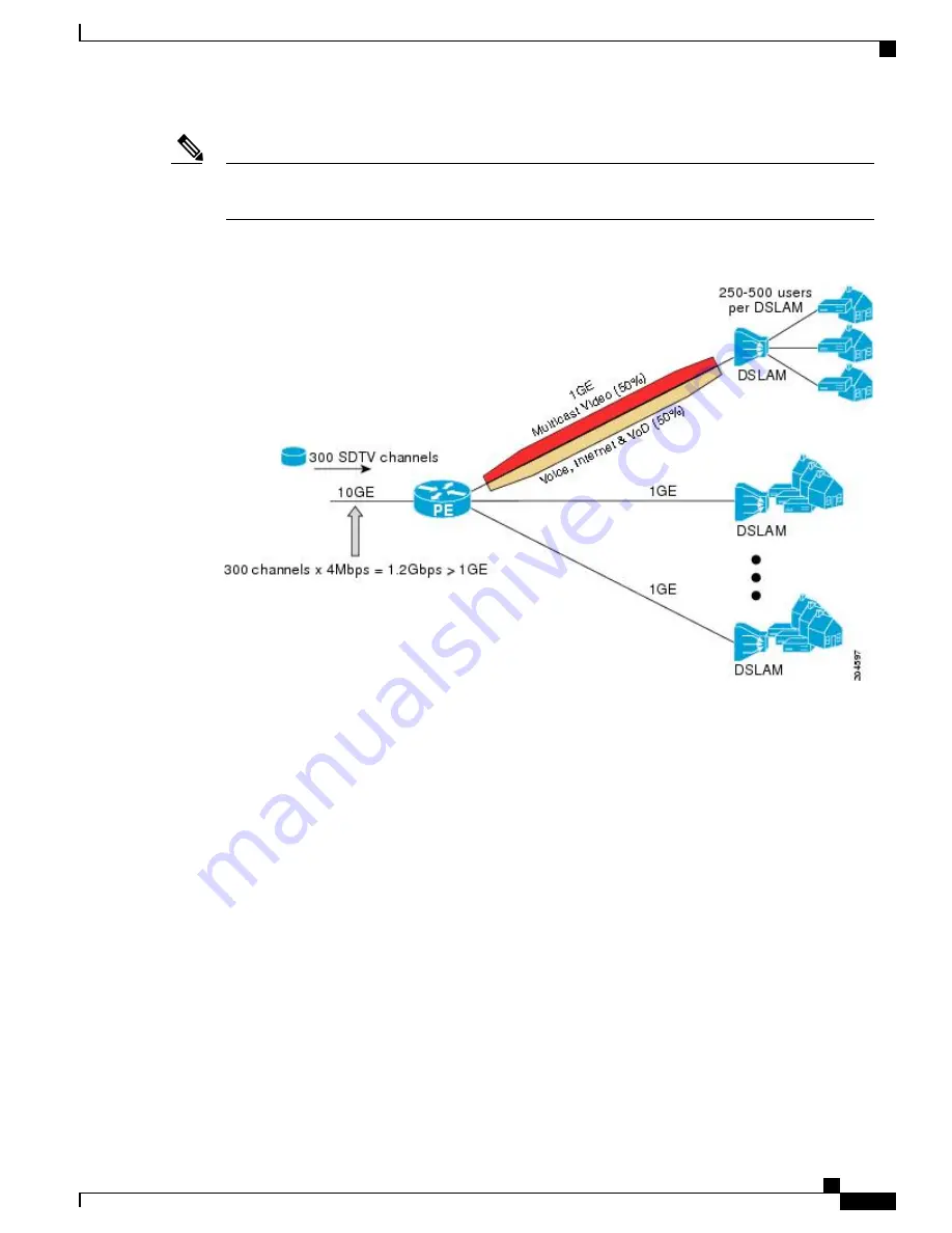
Figure 20: IGMP State Limit Example Topology
In this example, a service provider is offering 300 Standard Definition (SD) TV channels. Each SD channel
utilizes approximately 4 Mbps.
The service provider must provision the Gigabit Ethernet interfaces on the PE router connected to the Digital
Subscriber Line Access Multiplexers (DSLAMs) as follows: 50% of the link
’
s bandwidth (500 Mbps) must
be available to subscribers of the Internet, voice, and video on demand (VoD) service offerings while the
remaining 50% (500 Mbps) of the link
’
s bandwidth must be available to subscribers of the SD channel offerings.
Because each SD channel utilizes the same amount of bandwidth (4 Mbps), per interface IGMP state limiters
can be used to provide the necessary CAC to provision the services being offered by the service provider. To
determine the required CAC needed per interface, the total number of channels is divided by 4 (because each
channel utilizes 4 Mbps of bandwidth). The required CAC needed per interface, therefore, is as follows:
500Mbps / 4Mbps = 125 mroutes
Once the required CAC is determined, the service provider uses the results to configure the per IGMP state
limiters required to provision the Gigabit Ethernet interfaces on the PE router. Based on the network
’
s CAC
requirements, the service provider must limit the SD channels that can be transmitted out a Gigabit Ethernet
interface (at any given time) to 125. Configuring a per interface IGMP state limit of 125 for the SD channels
provisions the interface for 500 Mbps of bandwidth, the 50% of the link
’
s bandwidth that must always be
available (but never exceeded) for the SD channel offerings.
IP Multicast Routing Configuration Guide, Cisco IOS XE Release 3SE (Catalyst 3650 Switches)
OL-29890-01
355
IP Multicast Optimization: IGMP State Limit
Configuring IGMP State Limiters Example


