4-25
Cisco ASA 5585-X Adaptive Security Appliance Hardware Installation Guide
OL-22567-02
Chapter 4 Maintenance and Upgrade Procedures
Removing and Installing the Power Supply Module
Follow these steps to disconnect the source DC to the DC-input power supply and remove the DC
power-supply module:
Step 1
Set the power switch or circuit breaker to the off (0) position on the source DC circuit that feeds the
power supply that you are installing.
As an added precaution, place the appropriate safety flag and lockout devices at the source power circuit
breaker, or place a piece of adhesive tape over the circuit breaker handle to prevent accidental power
restoration while you are working on the circuit.
Step 2
Verify that the power switch on the power supply you are removing is in the STANDBY (
) position.
Step 3
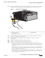
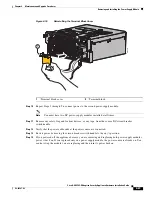
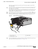
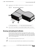
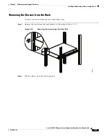
Remove the terminal block cover by simultaneously squeezing the left and right sides of the terminal
block, and at the same time pull the cover off the terminal block; set the cover aside (
Figure 4-21
).
Figure 4-21
Removing the Terminal Block Cover
Step 4
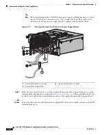
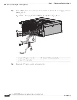
Using a 5/16-inch nut-driver, loosen and remove the four nut and lock-washer pairs from the DC power
lugs. Set the nuts and lock-washers aside (
Figure 4-22 on page 4-26
).
1
Terminal block cover
2
Terminal block
3
Terminal block cover clip
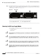
1150W DC
2
1
33
4552


