


4-16
Cisco ASA 5585-X Adaptive Security Appliance Hardware Installation Guide
OL-22567-02
Chapter 4 Maintenance and Upgrade Procedures
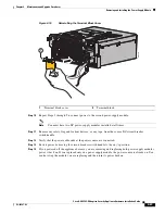
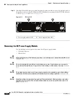
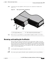
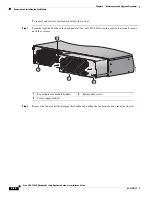
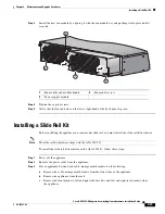
Removing and Installing the Power Supply Module
DC Power Supply Module
The ASA 5585-X ships with two DC power-supply modules
installed in a load balancing/sharing
configuration. This is the only supported DC power-supply module configuration. The load
balancing/sharing configuration ensures that if one DC power supply module fails, the other DC power
supply module assumes the full load until the failed power-supply module is replaced. To maintain air
flow, both bays must be populated by two DC power-supply modules.
You can install or replace either power-supply module without powering off the appliance, as long as
one power-supply module is active and functioning correctly.
Note
Only the ASA 5585-X SSP-60 supports either two AC or two DC power-supply modules. Do not mix
AC and DC power-supply modules in the same chassis.
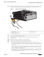
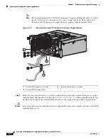
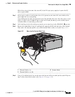
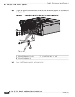
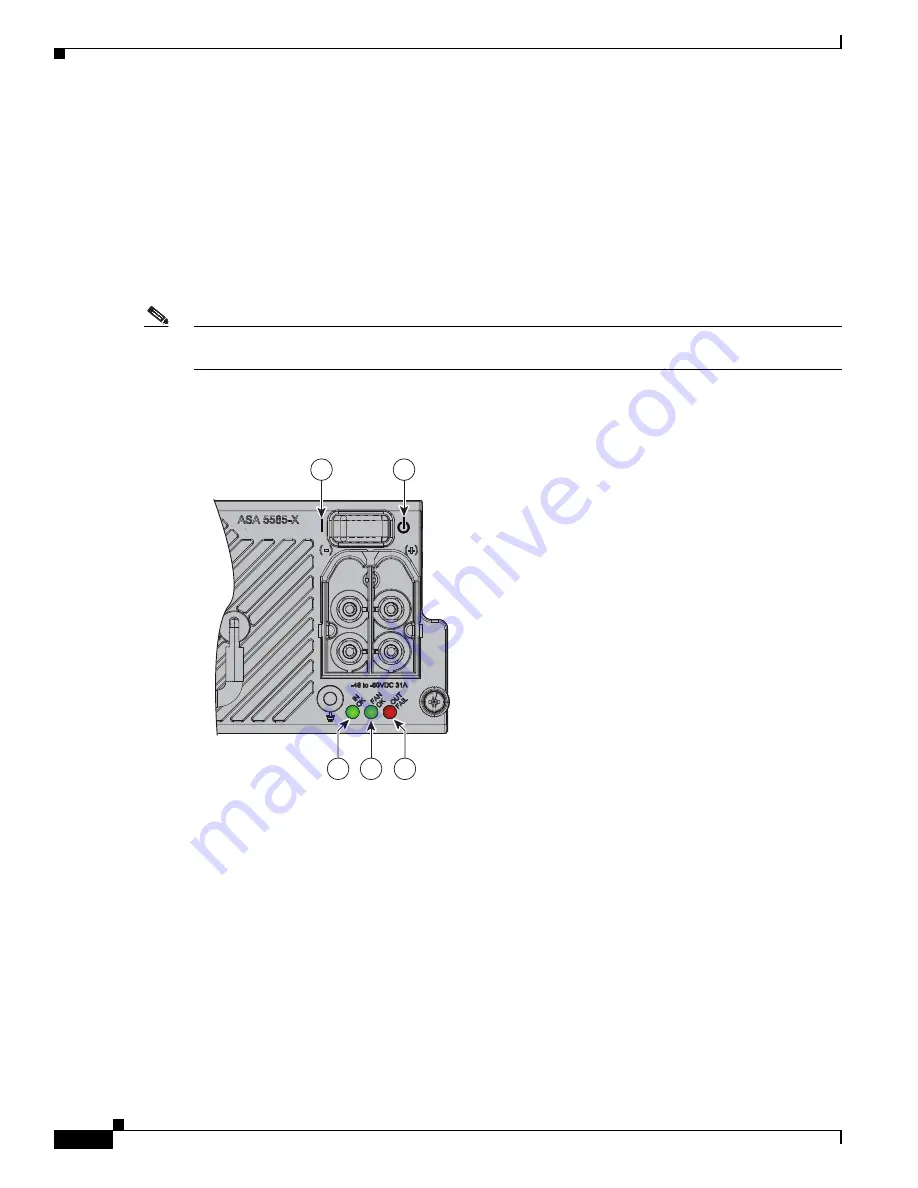
Figure 4-15
shows the DC power-supply module indicator lights and power-switch labels.
Figure 4-15
DC Power Supply Module Indicator Lights and Power Switch Labels
33
455
3
2
3
1
4
5
1150W DC


