


4-18
Cisco ASA 5585-X Adaptive Security Appliance Hardware Installation Guide
OL-22567-02
Chapter 4 Maintenance and Upgrade Procedures
Removing and Installing the Power Supply Module
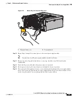
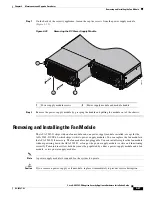
Step 2
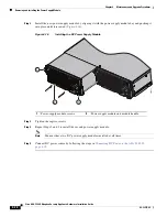
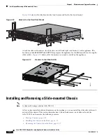
Install the new power-supply module by aligning it with the power-supply module bay and pushing it
into place until it is seated (
Figure 4-16
).
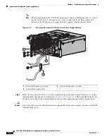
Figure 4-16
Installing the DC Power Supply Module
Step 3
Tighten the captive screws.
Step 4
Repeat Steps 2 and 3 to install the second power-supply module.
Note
You must have two DC power-supply modules installed at all times.
Step 5
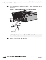
Connect DC power source by following the steps in
Connecting DC Power to the ASA 5585-X,
page 4-19
.
1
Power-supply module screws
2
Power-supply module and module handle
2
1
1
33
4517
115
0W
D
C
115
0W
D
C


