


4-24
Cisco ASA 5585-X Adaptive Security Appliance Hardware Installation Guide
OL-22567-02
Chapter 4 Maintenance and Upgrade Procedures
Removing and Installing the Power Supply Module
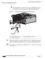
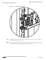
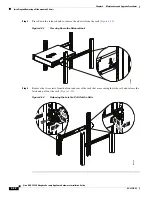
Step 15
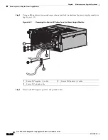
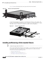
Check the PS0 and PS1 indicators on the front panel to make sure they are green. On the back panel of
the appliance, make sure the IN OK and the FAN OK indicators are green and the OUT FAIL indicator
is off (see
Figure 4-20
and
Table 4-4 on page 4-17
).
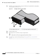
Figure 4-20
PS0 and PS1
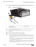
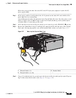
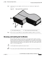
Removing the DC Power Supply Module
Use the following tools and parts to disconnect the DC power supply module:
•
5/16-inch nut-driver
•
M4 nut-driver
Warning
Before performing any of the following procedures, ensure that power is removed from the DC circuit.
Statement 1003
.
Warning
This unit is intended for installation in restricted-access areas. A restricted-access area can be
accessed only through the use of a special tool, lock and key, or other means of security.
Statement
1017
Warning
This product requires short-circuit (overcurrent) protection, to be provided as part of the building
installation. Install only in accordance with national and local wiring regulations.
Statement 1045
Warning
Hazardous voltage or energy may be present on DC power terminals. Always replace cover when
terminals are not in service. Be sure uninsulated conductors are not accessible when cover is in
place.
Statement 1075
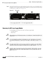
1
Power supply module (PS0)
2
Power supply module (PS1)
33
451
8
2
1
1150W DC
1150W DC


