4-10
Cisco ASA 5585-X Adaptive Security Appliance Hardware Installation Guide
OL-22567-02
Chapter 4 Maintenance and Upgrade Procedures
Installing and Removing Cisco ASA 5585-X Network I/O Modules
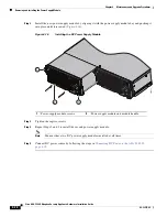
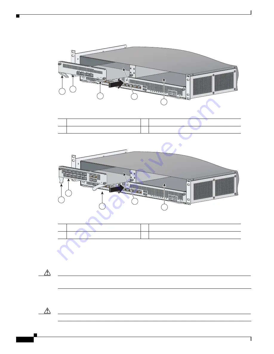
Figure 4-7
Installing a 4- or 8-Port 10-G Network I/O Module
Figure 4-8
Installing a 20-Port 1-G Network I/O Module
Step 6
Slide the network module into the slot until it is seated and push the ejection levers back into place.
Step 7
With your fingers, tighten the captive thumb screws.
Step 8
If you are installing only one network I/O module, install a slot cover on the empty slot bay to protect it.
Caution
You must install slot covers on all empty slots to maintain the proper air flow. This also prevents EMI,
which can disrupt other equipment.
Step 9
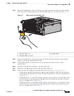
Install a SFP/SFP+ transceiver by aligning it with the I/O module port and sliding it into the port slot
until it locks into position (
Figure 4-9
).
Caution
Do not remove the optical port plugs from the SFP/SFP+ until you are ready to connect the cabling.
1
4- or 8-port 10-G network module
2
Ejection levers
3
Slot 2 left bay
4
Slot 1 right bay
PWR
BOO
T
ALARM ACT
VPN
PS1
HDD1
PS0
HDD0
USB
RESET
0
SFP1
SFP0
1
0
1
2
3
4
5
6
7
MGMT
0
1
AUX
CONSOLE
331651
1
2
4
2
3
1
20-port 1-G network I/O module
2
Ejection levers
3
Slot 2 left bay
4
Slot 1 right bay
PWR
BOO
T
ALARM ACT
VPN
PS1
HDD1
PS0
HDD0
USB
RESET
0
SFP1
SFP0
1
0
1
2
3
4
5
6
7
MGMT
0
1
AUX
CONSOLE
331867
1
2
4
2
3


